 language
Quick Aerospace Printed Circuit Board without MOQ
Aerospace printed circuit board technology enables flight-critical electronics to operate reliably under vibration, thermal cycling, and strict traceability requirements. This article explains what makes aerospace PCBs different, where teams get stuck when they need quick-turn builds without MOQ, and how to design, manufacture, and qualify boards without losing control of quality, cost, or schedule.
What usually goes wrong when you need quick aerospace boards without minimum order limits?
- Documentation and revision alignment consumes days.
- MOQ or NRE-style fees distort prototype economics.
- Material or finish approvals extend lead times.
- Late DFM feedback forces avoidable re-spins.
- Test scope and traceability remain unclear.
A viable quick-turn model depends on a disciplined, aerospace-correct process that stays controlled even at low quantities.
- Documentation is locked early with controlled change handling.
- Pricing is based on process and test scope, not volume.
- Qualified materials and proven stack-ups are prioritized.
- DFM is completed before tooling begins.
- Inspection, electrical test, and traceability are defined up front.
EBest Circuit (Best Technology) is a specialized PCB fabrication and PCBA manufacturer focused on complex, high-reliability boards. We support quick-turn, low-volume aerospace programs with disciplined DFM, controlled process execution, and documentation-driven traceability—without forcing MOQ constraints that slow early-stage development. If you have any PCB needs, pls feel free to contact us via sales@vn.danyupcbs.com.
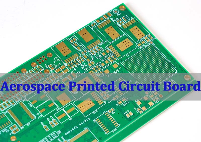
What Is an Aerospace Printed Circuit Board?
A quick aerospace printed circuit board is not simply a “better PCB.” It is a board built with reliability-first design rules, validated materials, controlled processes, and documentation that supports traceability—while still meeting tight prototype or low-volume schedules.
Key Points (What “Aerospace” Implies in Practice)
- Reliability target comes first: mechanical, thermal, and electrical margins are designed in, not “tested in later.”
- Tighter process control: plating, lamination, drill quality, and cleanliness are managed with higher scrutiny.
- Traceability expectation: material lots, process records, and test evidence matter as much as the Gerber.
- Verification emphasis: inspection and electrical test are defined to fit the risk profile.
- Change control discipline: revisions and deviations must be trackable and auditable.
Fast-Decision Table (Prototype Reality vs Aerospace Expectations)
| Item | Typical Prototype PCB | Aerospace Printed Circuit Board |
|---|---|---|
| Documentation | Minimal notes | Controlled traveler + revision mapping |
| Materials | “Available now” | Qualified options, recorded lots |
| Inspection | Visual sampling | Defined inspection scope + records |
| Test | Basic continuity | Electrical test aligned to risk |
| Change Handling | Informal | Controlled deviation / ECO discipline |
In short, an aerospace printed circuit board is defined as much by its controls and evidence as by its copper and laminate.
Key Performance Requirements That Differentiate Aerospace Printed Circuit Boards From Industrial PCBs
For quick-turn aerospace work without MOQ, the essential goal is to preserve reliability outcomes while compressing schedule. That requires knowing which performance requirements are non-negotiable and which can be optimized through smart design-for-manufacture choices.
- Thermal cycling tolerance: stack-up, resin system, and copper balance reduce stress and warpage.
- Vibration and mechanical robustness: via structures, pad designs, and component anchoring matter.
- Stable impedance and signal integrity: controlled dielectric and geometry consistency support predictable performance.
- High plating integrity: via wall quality and plating thickness support long-term reliability.
- Cleanliness and contamination control: ionic residue control supports insulation resistance stability.
- Consistent solderability: surface finish selection impacts assembly yield and rework behavior.
- Traceability-ready documentation: fast builds still need clean records and revision control.
Quick Tip List for Speed Without Compromise
- Standardize on proven stack-ups when possible to reduce engineering churn.
- Use pre-reviewed impedance structures for high-speed nets.
- Avoid “exotic” finishes unless the application requires them.
The practical difference is not “aerospace is expensive,” but “aerospace is evidence-based,” and evidence takes planning—even when you move fast.
How Aerospace PCB Design Standards Define Layout Rules, Stack-Up Strategy, and Reliability Margins?
Quick builds succeed or fail in design. Aerospace pcb design standards influence everything from annular ring targets and creepage strategy to stack-up symmetry and impedance planning. The fastest schedule is usually achieved by designing to a known-good process window from day one.
Design Rules That Most Often Impact Schedule
- Stack-up symmetry and copper balance: reduces bow/twist risk and improves lamination stability.
- Via strategy: avoid marginal aspect ratios; choose structures your vendor can repeat at speed.
- Annular ring and pad geometry: protect drill tolerance stack-up and improve yield.
- Clearance and creepage intent: align with operating voltage and environment, not generic defaults.
- Impedance planning: define targets, tolerance, and reference planes clearly to prevent iteration loops.
- Solder mask and assembly constraints: avoid mask slivers, define paste strategy for dense areas.
Compact Checklist (DFM-First for Quick Turn)
- Include controlled impedance notes only where needed and define measurement method.
- Specify finishes and thickness as ranges where acceptable, not single-point constraints.
- Provide fabrication drawing with revision clarity and controlled notes.
When aerospace pcb design standards are treated as a “design accelerator” rather than a compliance burden, you cut re-spins and protect the schedule.
Materials and Manufacturing Processes Used by Aerospace Printed Circuit Board Manufacturers
Aerospace Printed Circuit Board Manufacturers typically win or lose quick-turn performance on material readiness, process stability, and disciplined front-end engineering. The fastest path is not improvisation—it is using validated options that the factory can run predictably.
Materials Often Selected for Quick, Reliable Builds
- High-Tg FR-4 systems: strong baseline for many avionics and control boards.
- Low-loss laminates (when required): used when signal integrity demands it.
- Copper weight selection: balances current handling and manufacturability.
- Surface finish choice: aligned to assembly plan and shelf-life needs.
- Prepreg compatibility: avoids lamination surprises and resin starvation issues.
Manufacturing Process Steps That Most Affect Speed and Reliability
- Front-end CAM and DFM validation: compresses iteration cycles.
- Lamination control: pressure/temperature profiling impacts voiding and thickness stability.
- Drilling quality management: hole integrity supports plating performance.
- Plating process control: via reliability depends heavily on consistent deposition.
- Solder mask and legend control: protects assembly yield and inspection clarity.
- Electrical test and inspection plan: defined scope prevents last-minute debates.
If you need an aerospace PCB manufacturer that supports quick prototypes without MOQ, the “secret” is predictable options—materials and processes that are already understood, controlled, and documented.
Understanding Aerospace Printed Circuit Board Cost Drivers in Low-Volume, High-Reliability Programs
Aerospace printed circuit board cost is rarely driven by raw laminate alone. In quick-turn, no-MOQ programs, the biggest cost drivers tend to be engineering time, special process controls, inspection scope, and the degree of documentation and traceability required.
The Core Cost Drivers
- Engineering and tooling overhead: CAM time, impedance validation, drill programs, and traveler setup.
- Material selection and availability: qualified materials may have longer supply chains.
- Layer count and complexity: more layers, tighter geometries, and special structures raise process time.
- Inspection requirements: higher inspection scope increases labor and cycle time.
- Test strategy: full electrical test, coupons, and reporting add cost but reduce risk.
- Documentation and traceability: records, lot tracking, and controlled change handling take effort.
Quick-Decision Table (Where Costs Typically Spike)
| Driver | What Increases Cost | How To Keep It Controlled |
|---|---|---|
| Complexity | tight spacing, high layer count | align design to proven rules |
| Materials | specialty laminates | choose qualified alternates where acceptable |
| Inspection | expanded scope, reporting | define risk-based scope early |
| Test | added coupons, tighter limits | specify only what the program needs |
| Speed | priority processing | prevent rework with front-loaded DFM |
In low-volume aerospace builds, cost control comes from clarity: define intent, avoid ambiguity, and prevent rework.
Typical Applications of Printed Circuit Boards for Aerospace in Avionics, Power, and Control Systems
Printed circuit boards for aerospace commonly support systems where failure is not merely inconvenient—it can be mission-impacting. The application context also influences how you define stack-up, finish, and verification scope for quick-turn builds.
Common Aerospace Application Categories
- Avionics processing and I/O: stable impedance and noise control often dominate.
- Power conversion and distribution: copper weight, thermal design, and creepage become central.
- Actuation and control loops: reliability and deterministic performance matter.
- Sensors and data acquisition: low-noise layout and grounding strategy are critical.
- Communication subsystems: material loss characteristics may be important.
- Cabin and environmental control electronics: mixed-signal layout and robustness.
Practical Design Focus by Application
- Avionics: reference plane integrity, return path control, connector reliability.
- Power: thermal paths, via arrays, copper balance, creepage discipline.
- Control: stable grounding, decoupling placement, predictable impedance where needed.
The faster you align application requirements to the build plan, the more realistic “quick without MOQ” becomes.
How to Qualify an Aerospace PCB Manufacturer for Certification, Traceability, and Long-Term Supply?
Selecting an aerospace PCB manufacturer for quick-turn builds is a risk management decision. You need speed, but you also need confidence that the build will be repeatable, auditable, and stable when prototypes scale into production.
Qualification Criteria That Matter Most
- Document control maturity: traveler discipline, revision control, deviation handling.
- Process capability fit: can the factory repeatedly produce your geometry and stack-up?
- Traceability coverage: material lot tracking, process records, inspection evidence.
- Test and inspection competence: electrical test capability, inspection scope clarity.
- DFM responsiveness: feedback speed and quality before production starts.
- Supply continuity plan: material alternatives, second-source thinking, capacity planning.
Quick “Go/No-Go” Questions
- Can you show how you manage controlled changes across quick-turn builds?
- Do you provide clear evidence of inspection and electrical test completion?
- Can you support low volume today and scale later without changing the core process?
A capable aerospace PCB manufacturer makes quick-turn possible because the process is already stable; speed comes from discipline, not shortcuts.
Market Structure and Regional Supply Differences in the Aerospace Printed Circuit Board Market
The aerospace printed circuit board market is shaped by qualification expectations, supply chain policies, and regional manufacturing ecosystems. For quick-turn, no-MOQ builds, the practical takeaway is that regional supply differences affect lead time, material access, and the level of documentation customers expect.
Key Market Dynamics Relevant to Quick Turn
- Low-volume reality: many aerospace programs start with prototypes, NPI, or limited builds.
- Qualification-driven supply: approved processes and evidence requirements influence vendor selection.
- Material availability differences: certain laminates and finishes may source faster in some regions.
- Documentation expectations: traceability and reporting depth vary by customer and region.
- Cost structure differences: labor, compliance overhead, and test scope affect pricing.
Where “Printed Circuit Board Manufacturers USA” Often Enters the Conversation
- Procurement policies may prefer or require regional sourcing.
- Delivery time targets may favor domestic builds for urgent iterations.
- However, capability alignment and documentation quality can outweigh geography in practice.
The best quick-turn outcome typically comes from matching program constraints to a supplier’s proven process window—then keeping changes controlled and documented.
Aerospace printed circuit board manufacturing delivers the reliability and traceability foundation that flight and mission electronics depend on, even when you need quick-turn builds without MOQ. This article covered the core aerospace PCB requirements, the role of aerospace pcb design standards, the key cost drivers, typical applications, how to qualify an aerospace PCB manufacturer, and how market structure impacts lead time and supply decisions. EBest Circuit (Best Technology) supports fast, low-volume aerospace programs with disciplined DFM, controlled processes, and documentation-driven traceability—without forcing MOQ barriers that slow iteration. If you have any inquiry, pls feel free to contact us at sales@vn.danyupcbs.com.
FAQs
What Is PCB in Aerospace?
In aerospace, PCB refers to a printed circuit board used in systems that typically demand higher reliability margins, stronger traceability, and more controlled manufacturing and verification than general industrial electronics.
What Materials Are Used in Aerospace PCB?
Aerospace PCB material choices often include high-Tg FR-4 systems for many applications, with specialized laminates selected when signal integrity, thermal behavior, or environmental limits require them. The most important factor is not novelty—it is material stability, documented sourcing, and compatibility with a controlled build process.