 language
ICT Tester: What is it? ICT Testing vs FCT Testing
An ICT tester helps verify that each component on a PCB is correctly placed, soldered, and electrically sound. Unlike surface inspection methods that only check visual defects, ICT goes deep into the board’s electrical integrity. It measures resistance, capacitance, and signal paths to catch problems early—before they evolve into costly rework or field failures.
Whether for consumer electronics, automotive systems, or aerospace devices, ICT testing stands as one of the most reliable ways to maintain consistent product quality in large-scale manufacturing.
What is an ICT Tester?
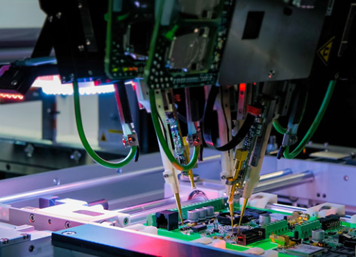
An ICT tester (In-Circuit Tester) is a specialized piece of equipment used to perform electrical testing on fully assembled PCBs. It uses a bed-of-nails fixture, consisting of thousands of spring-loaded probes that make contact with test points on the board. These probes apply electrical signals—voltage or current—to measure whether components behave within the expected tolerance.
The test results are compared against a “golden board” or the circuit’s reference design. If a measured value deviates from the expected range, the tester flags it as a defect.
ICT systems typically include four key elements:
1. Test Fixture: The mechanical interface holding probes that physically contact the PCB.
2. Measurement Unit: A system of precision instruments that generate signals and capture electrical responses.
3. Controller & Software: A computer that runs the test sequences and interprets measurement data.
4. User Interface: Displays test outcomes, diagnostics, and failure analysis.
These systems are capable of verifying hundreds of nodes within seconds, making them indispensable in high-volume PCB production lines.
What is the Function of ICT Tester?
The main function of an ICT tester is to ensure that every electrical connection and component on a PCB operates correctly. It does this by executing a sequence of tests designed to evaluate various parameters:
- Continuity Testing: Checks for open circuits or broken traces.
- Short-Circuit Detection: Identifies unintended connections between nets or components.
- Component Verification: Measures resistance, capacitance, and inductance to confirm component value and orientation.
- IC Testing: Uses vectorless or boundary-scan methods to verify the presence and connectivity of integrated circuits.
- Power Rail Validation: Ensures supply voltage and ground paths are not shorted before power-up.
- Programming & Calibration: In advanced setups, the ICT tester can also program microcontrollers and calibrate analog circuits automatically.
Importance of ICT Testing in Circuit Board
The importance of ICT testing extends far beyond defect detection—it is about process control, reliability, and cost optimization. In modern electronics manufacturing, where production runs can involve thousands of boards per day, manual inspection is not enough.
ICT testing electronics bring several critical benefits:
- Early Fault Detection: Catching defects right after assembly avoids costly downstream failures.
- Data-Driven Quality Control: Collected test data helps engineers identify recurring process issues, such as soldering temperature deviations or placement errors.
- Reduced Rework: Faulty boards can be quickly diagnosed and repaired, improving throughput.
- Enhanced Customer Confidence: Delivering consistently tested and verified products strengthens trust and brand reliability.
In industries like automotive and aerospace—where safety and durability are paramount—ICT testing isn’t optional; it’s mandatory. The structured electrical verification guarantees that every board leaving the factory is built according to strict performance standards.
Advantage and Disadvantage of ICT Testing
Advantages of ICT Testing
- High Accuracy: ICT provides component-level precision. It can detect even subtle variations in resistor values or capacitor leaks that might cause intermittent failures.
- Speed and Repeatability: Once a fixture is built, testing time per board is typically under 10 seconds, perfect for large production volumes.
- Comprehensive Diagnostics: Faults are not only detected but also located. Engineers know exactly which pad or component failed.
- Automation Capability: ICT can be fully automated and integrated into SMT production lines for inline testing.
- Data Traceability: Test results can be stored for traceability—essential for industries requiring certification, such as medical or automotive electronics.
Disadvantages of ICT Testing
Despite its strengths, ICT also comes with some limitations:
- High Fixture Cost: Custom test fixtures with thousands of probes can cost thousands of dollars. This setup is economical only for large production runs.
- Limited High-Frequency Testing: ICT focuses on static and low-frequency electrical parameters. It cannot evaluate timing-dependent functions or RF behavior.
- Fixture Maintenance: Over time, probe tips wear out or get contaminated with flux residues, requiring regular cleaning or replacement.
- Design Constraints: The PCB must include test pads at accessible points. Without proper design-for-test (DFT) considerations, ICT coverage drops significantly.
Even with these drawbacks, the benefits often outweigh the costs—especially when long-term reliability and efficiency are priorities.
ICT Testing vs FCT Testing
ICT (In-Circuit Testing) and FCT (Functional Circuit Testing) complement each other in the PCB production process, but they serve different purposes.
- ICT testing verifies how the board is built—checking that every component is placed correctly and functions within specification. It’s a structural test, focusing on electrical integrity before power-up.
- FCT testing verifies how the board performs—it powers up the entire circuit to see if it operates according to its design function.
Here’s a quick comparison:
| Aspect | ICT Testing | FCT Testing |
| Test Type | Structural | Functional |
| Scope | Components and connections | Entire circuit operation |
| Power Requirement | Usually unpowered | Powered (live circuit) |
| Fault Coverage | Open/short, missing, wrong, polarity | Firmware, timing, performance |
| Fixture Cost | High | Moderate |
| Speed | Very fast | Slower |
| Ideal Use | Mass production | Final verification |
In practice, manufacturers use both ICT and FCT together for complete quality control. ICT filters out assembly issues, while FCT validates end functionality—creating a two-stage safety net against defects.
Components Tested in In-Circuit Testing
ICT testing can evaluate nearly every passive and active component on a circuit board, including:
1. Resistors: Verified for correct resistance and placement. Even a 1% tolerance deviation can be identified.
2. Capacitors: Measured for capacitance and leakage. Detects incorrect values or reversed polarity in electrolytics.
3. Inductors: Checked for continuity and expected inductance range.
4. Diodes & LEDs: Tested for correct forward voltage and orientation.
5. Transistors & MOSFETs: Verified for junction integrity and pin configuration.
6. Connectors: Ensured to have complete continuity and correct grounding.
Some advanced ICT systems even integrate boundary-scan testing (JTAG) to access signals within dense BGA packages, which are otherwise unreachable by physical probes.
Defects ICT Test Can Detect in PCBs
ICT can uncover a wide variety of electrical and assembly defects. Some of the most common include:
- Open Circuits: Caused by broken traces or poor solder joints.
- Short Circuits: Due to solder bridges between adjacent pads.
- Incorrect Component Values: Resistors or capacitors with wrong specifications.
- Missing Components: Empty pads due to misfeed or placement error.
- Polarity Errors: Especially in diodes, electrolytic capacitors, and LEDs.
- Lifted Pads: When solder doesn’t bond properly to the pad.
- Unprogrammed or Faulty ICs: Detected through boundary scan or vectorless tests.
Detecting these defects early in the production line not only reduces rework costs but also improves the manufacturer’s yield rate and delivery reliability.
Fixture Design and Test Principle
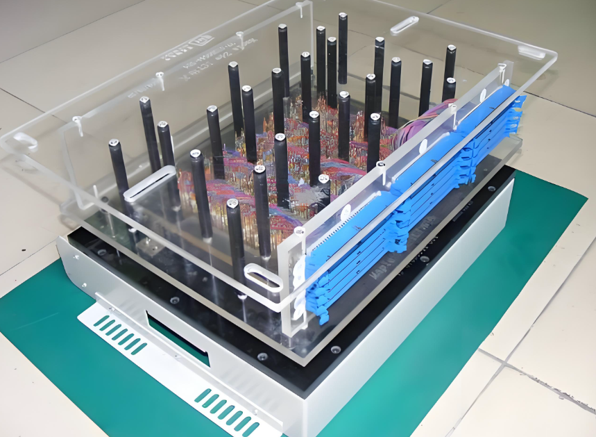
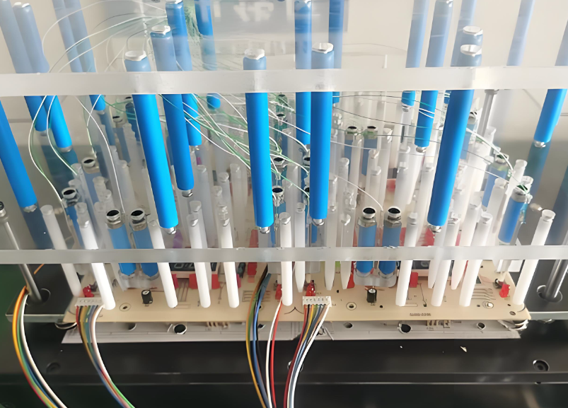
The test fixture is a critical component of any ICT setup. It’s a mechanical frame fitted with spring-loaded probes (known as “pogo pins”) that make contact with the PCB’s test pads.
There are two major types of fixtures:
1. Vacuum Fixture: Uses negative air pressure to pull the PCB firmly against the probe bed, ensuring stable contact.
2. Mechanical Clamper: Uses pneumatic or mechanical arms to press the board into position, suitable for double-sided testing.
Each probe connects to a measurement channel within the ICT system, allowing simultaneous testing of multiple points. The probes must align perfectly with test pads, which are typically 50–100 mil in diameter and evenly distributed across the board.
Design-for-Test (DFT) rules are essential when designing a PCB for ICT:
- Provide accessible test pads for all key nets.
- Avoid placing tall components near test points.
- Ensure adequate pad spacing to prevent shorting.
The testing principle follows Ohm’s Law and circuit theory. The ICT injects known current or voltage into specific nodes and measures the response to calculate actual component parameters. For instance, if the resistance across two nodes deviates from its nominal value, it indicates a potential fault such as an open or short.
Common Used In-Circuit Test Software
ICT testers rely on powerful software platforms to design, control, and analyze tests. Some of the most common in circuit test software include:
1. Keysight 3070 (formerly Agilent): A gold standard in the industry, widely used for both analog and digital circuit testing. It supports boundary-scan integration and flexible test development.
2. Teradyne TestStation: Known for high-speed testing and parallel processing, making it ideal for automotive and telecom applications.
3. SPEA Flying Probe Systems: Great for prototype or low-volume production without the need for expensive fixtures.
4. Takaya APT Series: Offers fixtureless testing with highly precise probe positioning and quick changeover.
5. JTAG Technologies Software: Used to enhance test coverage for dense PCBs, allowing access to BGA pins and internal logic.
At Best Technology, ICT testing forms an integral part of our PCB manufacturing and assembly process. Every board passes through automated optical inspection (AOI) and ICT verification before reaching functional testing.
We use advanced in circuit test software combined with programmable test fixtures to evaluate high-density, multi-layer PCBs. Whether for consumer electronics, automotive controllers, or medical devices, our ICT procedures provide accurate and repeatable test results.
If your project requires ICT testing electronics with professional engineering support and reliable quality management, Best Technology delivers tailored PCB testing and fabrication solutions backed by proven industry standards.