 language
SMD vs SMT: Key Differences and How SMT Assembly Works
SMT (Surface Mount Technology) refers to the manufacturing method used to mount electronic components directly onto the surface of a PCB. SMD (Surface Mount Device) refers to the electronic components specifically designed for this technology.
Today, most electronic devices—from smartphones and laptops to automotive control systems and industrial equipment—rely heavily on SMD components and SMT assembly processes. Understanding how SMD and SMT work together helps engineers design better PCBs and helps companies choose the right manufacturing partner.
What Does SMT Stand For?
SMT stands for Surface Mount Technology. It is a manufacturing technique used to mount electronic components directly onto the surface of a printed circuit board rather than inserting leads through holes.
Surface mount technology was developed to support the growing need for smaller, faster, and more efficient electronic devices. Before SMT became popular, most electronic assemblies used through-hole technology (THT). In through-hole assembly, component leads must pass through drilled holes in the PCB and then be soldered on the opposite side.
Instead of using leads that pass through the board, SMT components are placed directly on copper pads located on the PCB surface. After placement, solder paste and controlled heating permanently attach the components.
Key characteristics of SMT include:
- Components mounted directly on the board surface
- Automated assembly using pick-and-place machines
- Smaller component packages
- Higher circuit density
- Faster production speed
Because SMT allows thousands of components to be assembled quickly and accurately, it has become the dominant PCB assembly method in modern electronics manufacturing.
What Does SMT Stand For?
What Does SMD Stand For?
SMD stands for Surface Mount Device. These are the electronic components designed specifically for surface mount technology.
Unlike traditional components with long leads, SMD components are compact and designed to sit directly on the PCB surface. Their terminals connect to copper pads through solder joints formed during the SMT assembly process.
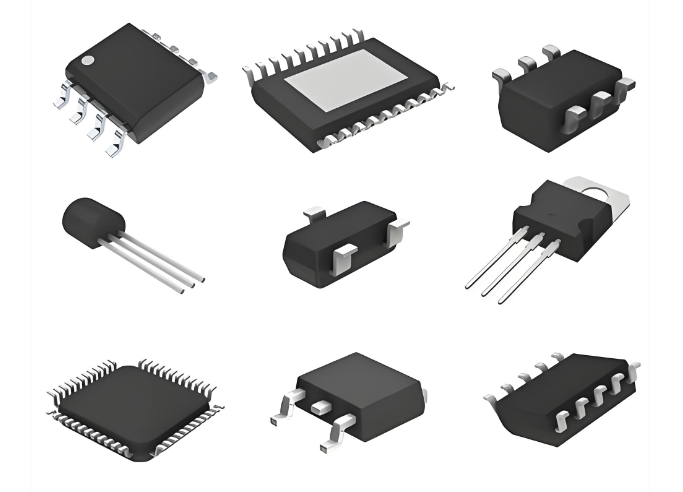
SMD components are widely used in nearly all modern electronic products. They are available in a wide range of package types and functions.
Common types of SMD components include:
- SMD resistors
- SMD capacitors
- SMD inductors
- SMD diodes
- Integrated circuits (ICs)
- Transistors and MOSFETs
Typical SMD package formats include:
- 0603 / 0805 resistors and capacitors
- SOIC (Small Outline Integrated Circuit)
- QFN (Quad Flat No-lead)
- BGA (Ball Grid Array)
- SOT packages for transistors
These components are optimized for automated placement, making them ideal for high-volume manufacturing.
What Does SMD Stand For?
What Is the Difference Between SMT and SMD?
Although the terms SMD and SMT are closely related, they refer to different concepts in electronics manufacturing.
The simplest way to understand the difference is:
- SMT = the assembly technology
- SMD = the components used in that technology
The relationship between them is similar to the relationship between a production process and the materials used in that process.
| Item | SMT (Surface Mount Technology) | SMD (Surface Mount Device) |
| Definition | A PCB assembly technology used to mount components directly on the PCB surface | Electronic components designed for surface mounting |
| Type | Manufacturing process | Electronic component |
| Function | Method used to assemble components on PCBs | Devices mounted using SMT |
| Industry Role | Describes the production technique | Describes the parts used in that technique |
| Example | SMT assembly line, SMT process | SMD resistor, SMD capacitor |
| Design Consideration | Focuses on manufacturing process and equipment | Focuses on package design and electrical function |
| Usage in PCB Assembly | Used during PCB manufacturing | Used as electronic components in circuits |
| Equipment Involved | Stencil printer, pick-and-place machine, reflow oven | No equipment required (they are the parts placed on PCB) |
| Package Types | Not applicable | QFN, BGA, SOIC, SOT, 0603, 0402, etc. |
| Engineering Focus | Assembly process optimization | Component selection and PCB footprint design |
| Impact on Production | Determines production speed and efficiency | Determines circuit functionality |
| Typical Discussion Context | Manufacturing, assembly lines, PCB factories | Electronic components and circuit design |
In simple terms, SMT is the method, while SMD is the component used in that method.
Understanding this distinction helps prevent confusion when discussing PCB design, assembly processes, or manufacturing capabilities.
Why Are SMD Components Used in SMT Assembly?
SMD components are widely used because they support efficient and compact electronic designs. Their structure makes them perfectly suited for automated surface mount assembly.
One major advantage is size reduction. SMD components are much smaller than traditional through-hole components. This allows engineers to design compact PCBs that fit inside small electronic products.
Another advantage is high-density circuit layout. Because SMD components occupy less space, more components can be placed on a single PCB. This is essential for complex electronics such as smartphones, communication devices, and medical instruments.
Additional benefits include:
- Improved electrical performance
- Reduced lead inductance
- Better high-frequency characteristics
- Lower manufacturing cost in large volumes
For these reasons, SMT assembly using SMD components has become the standard method for PCB manufacturing worldwide.
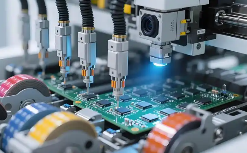
How Does the SMT Assembly Process Work?
The SMT assembly process consists of several automated steps that ensure accurate placement and reliable soldering of components. The process typically includes the following stages.
1. Solder Paste Printing
A metal stencil is used to apply solder paste onto the copper pads of the PCB. The paste contains tiny solder particles mixed with flux.
Accurate paste deposition is essential because it determines the quality of the final solder joints.
2. Component Placement
A pick-and-place machine positions SMD components onto the solder paste locations. These machines use vacuum nozzles and high-speed vision systems to ensure precise placement.
Modern pick-and-place machines can place more than 50,000 components per hour.
3. Reflow Soldering
The PCB passes through a reflow oven where controlled heating melts the solder paste. Once the solder cools, it forms solid electrical and mechanical connections between the components and PCB pads.
4. Inspection and Quality Control
After soldering, inspection equipment checks assembly quality.
Common inspection methods include:
- Automated Optical Inspection (AOI)
- X-ray inspection
- In-Circuit Testing (ICT)
- Functional testing
These inspections ensure the PCB assembly meets electrical and mechanical reliability standards.
What Machines Are Used in SMT Manufacturing?
A professional SMT production line uses specialized equipment to ensure speed, accuracy, and reliability.
The main machines used in SMT manufacturing include:
1. Solder Paste Printer
This machine applies solder paste onto PCB pads through a stainless steel stencil. Precise printing ensures consistent solder joints.
2. Pick-and-Place Machine
The pick-and-place machine is the core of SMT assembly. It picks components from reels or trays and places them onto the PCB.
High-speed models can place tens of thousands of components per hour.
3. Reflow Oven
A reflow oven heats the PCB according to a controlled temperature profile. This melts the solder paste and permanently attaches components.
Typical peak temperatures for lead-free solder reach 240–250°C.
4. Inspection Systems
Inspection equipment helps detect assembly defects early.
Common systems include:
- AOI (Automated Optical Inspection)
- SPI (Solder Paste Inspection)
- X-ray inspection for BGA packages
Together, these machines form a fully automated SMT assembly line.
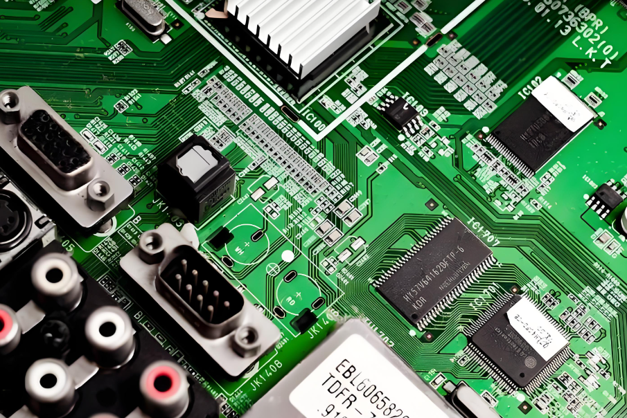
SMD vs Through Hole: What Is the Difference?
SMD (Surface Mount Device) and Through-Hole components represent two different ways electronic components are mounted on a printed circuit board. SMD components are soldered directly onto the PCB surface using SMT assembly, while through-hole components have leads inserted into drilled holes and soldered on the opposite side of the board.
Below is a more comprehensive comparison between SMD and Through-Hole components.
| Item | SMD (Surface Mount Device) | Through Hole |
| Mounting Method | Mounted directly on PCB surface | Leads inserted through drilled holes |
| Assembly Technology | SMT (Surface Mount Technology) | THT (Through-Hole Technology) |
| Component Size | Much smaller | Larger packages |
| PCB Space Usage | High component density | Requires more board space |
| Manufacturing Speed | Highly automated | Often partially manual |
| Production Cost | Lower in large-volume production | Higher due to manual steps |
| Mechanical Strength | Moderate | Very strong mechanical bonding |
| Electrical Performance | Better for high-frequency circuits | Higher parasitic inductance |
| PCB Design Complexity | Requires precise pad design | Simpler layout in some cases |
| Repair and Rework | More difficult | Easier to replace manually |
| Thermal Performance | Moderate heat dissipation | Can handle higher current and heat |
| Typical Components | Small resistors, capacitors, ICs, sensors | Connectors, transformers, large capacitors |
| Package Examples | 0402, 0603, QFN, BGA, SOT, SOIC | DIP, axial resistor, radial capacitor |
| Assembly Equipment | Pick-and-place machines, reflow ovens | Wave soldering or manual soldering |
Although SMT dominates modern electronics manufacturing, through-hole technology still plays an important role in applications requiring strong mechanical connections or high power handling.
What Are Common SMT Soldering Defects?
Even with advanced automation, soldering defects can occur during SMT assembly. Identifying these issues early helps improve product reliability. Some of the most common SMT defects include:
1. Solder Bridging
Solder accidentally connects two adjacent pads, creating an electrical short circuit. This usually happens due to excessive solder paste or stencil misalignment.
2. Tombstoning
A small passive component stands upright during reflow soldering. Uneven heating or pad design often causes this issue.
3. Cold Solder Joint
A solder joint appears dull and grainy due to insufficient heating. Cold joints may cause intermittent electrical connections.
4. Insufficient Solder
Too little solder can weaken the electrical connection between the component and PCB pad.
5. Voids in BGA Solder Balls
Air pockets may form inside BGA solder joints. These voids reduce thermal conductivity and mechanical strength.
If you want to know more defects occur in PCB assembly, please view our another article: Common 13 Types of Soldering Defects in PCB Assembly
How to Design a PCB for SMD Components?
Designing a PCB for SMT assembly requires careful attention to layout, pad design, and manufacturing compatibility. Several design guidelines help ensure reliable assembly.
First, engineers must use correct component footprints. Each SMD package requires specific pad sizes and spacing defined by IPC standards.
Second, proper solder mask design prevents solder bridging between pads. Adequate spacing ensures reliable solder joints.
Third, designers should consider thermal management. Components such as power regulators or processors may require thermal vias or copper planes to dissipate heat.
Why Choose a Professional SMT Assembly Manufacturer?
Choosing an experienced SMT assembly manufacturer is essential for reliable PCB production. Professional manufacturers offer advanced equipment, engineering expertise, and strict quality control processes.
An experienced provider can help customers with:
- DFM (Design for Manufacturing) analysis
- BOM optimization
- Component sourcing
- PCB fabrication and PCBA assembly
- Functional testing and inspection
Best Technology provides one-stop PCB and PCBA services for customers worldwide. With over 20 years of industry experience, the company supports engineers with professional manufacturing solutions and flexible production options.
EBest integrates PCB fabrication, component sourcing, SMT assembly, and testing to help customers accelerate product development and reduce manufacturing complexity.
For inquiries or technical support, feel free to contact: sales@vn.danyupcbs.com
FAQs
1. Is SMD the same as SMT?
No. SMD refers to the electronic component, while SMT refers to the manufacturing process used to mount those components onto the PCB.
2. What does SMT mean in PCB assembly?
SMT stands for Surface Mount Technology. It is the process of mounting electronic components directly onto the surface of a printed circuit board.
3. What is the difference between SMT and through-hole technology?
SMT places components directly on the PCB surface, while through-hole technology requires component leads to pass through drilled holes in the board.
4. Why are SMD components smaller?
SMD components are designed without long leads and use compact package structures. This allows manufacturers to build smaller electronic devices.
5. Can SMT components be repaired?
Yes. SMT components can be repaired using specialized rework equipment such as hot-air stations, infrared heaters, or BGA rework systems.
6. What industries use SMT technology?
SMT is widely used in many industries including:
- Consumer electronics
- Automotive electronics
- Medical devices
- Industrial control systems
- Telecommunications equipment
- Aerospace and defense systems