 language
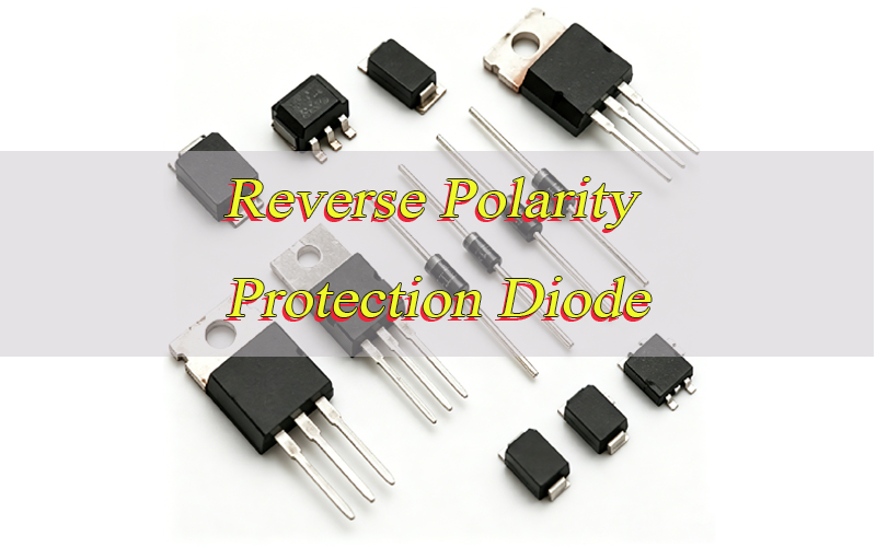
How to Choose a Reverse Polarity Protection Diode?
Have you ever wondered how a reverse polarity protection diode prevents instant damage in electronic circuits? A wrong power connection can quickly damage ICs, capacitors, batteries, and power modules, especially in compact PCB layouts and DC-powered devices.
A reverse polarity protection diode helps block or redirect harmful current when the power supply is connected backward. This simple protection method is widely used in automotive electronics, industrial devices, battery systems, LED drivers, and communication equipment.
Many modern products also combine reverse polarity protection diode solutions with MOSFETs, fuses, or Schottky designs to improve efficiency and thermal performance. Understanding how these protection methods work can help improve circuit reliability and reduce repair risks.
What Is a Reverse Polarity Protection Diode?
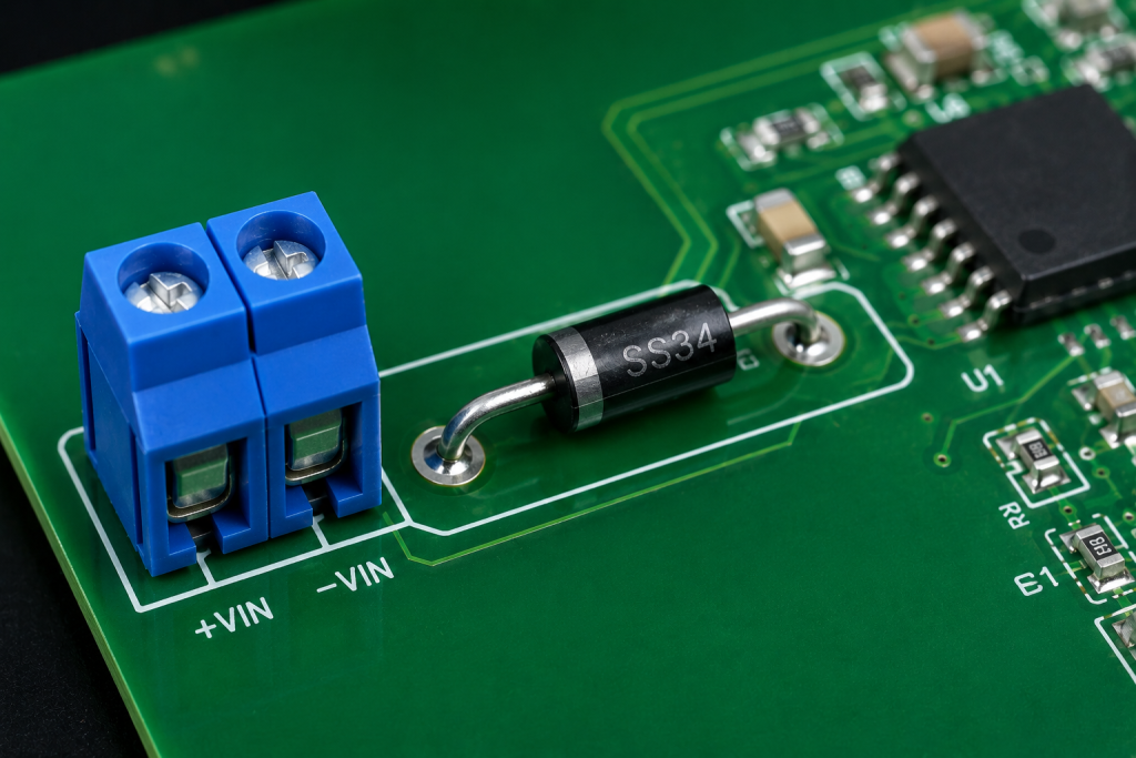
A reverse polarity protection diode is a component installed at the power input side of a circuit. Its main function is to stop electrical current when the positive and negative terminals are accidentally reversed.
This protection method is commonly used in low-voltage DC systems, battery-powered products, and automotive electronics. Without protection, reverse voltage may destroy sensitive components within seconds.
Most protection circuits use either a series diode or a parallel diode with a fuse. Some advanced systems also use MOSFET-based ideal diode designs for lower voltage drop and better efficiency.
Because of its simple structure and stable performance, diode-based reverse voltage protection remains popular in many PCB applications.
Why Is Reverse Polarity Protection Important in Electronic Circuits?
Power connection mistakes happen frequently during assembly, maintenance, battery replacement, or field installation. Even a short reverse connection can damage expensive components.
Modern electronic systems often use low-voltage ICs and compact PCB traces. These devices usually have very limited tolerance against reverse voltage conditions.
Reverse polarity protection helps reduce risks such as:
- Burned ICs
- Damaged capacitors
- Melted PCB traces
- Battery overheating
- Power supply failure
- Short-circuit damage
This protection is especially important in automotive systems, industrial controllers, communication equipment, and portable electronics. Adding a protection device at the power input stage can greatly improve long-term circuit stability.
How Does a Reverse Polarity Protection Diode Work?
A reverse polarity protection diode controls the direction of current flow in a circuit. When the power supply is connected correctly, current flows normally through the circuit. If the positive and negative terminals are reversed, the diode blocks the current to protect electronic components from reverse voltage damage.
In a series protection circuit, the diode is connected in line with the power input. Under normal polarity, the diode allows current to pass through the circuit. When the polarity is reversed, the diode becomes reverse-biased and immediately stops current flow. This method is simple and commonly used in low-voltage electronic products.
A Schottky diode is often used because it has a lower voltage drop than a standard silicon diode. Lower voltage loss helps reduce heat generation and improve power efficiency, especially in 5V and 12V DC circuits.
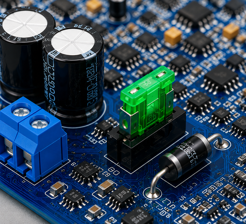
Another common method is parallel protection with a fuse. In this design, the diode is connected across the power rails. During reverse polarity, the diode conducts heavily and causes the fuse to disconnect the circuit quickly, preventing damage to the PCB and power components.
Some high-efficiency circuits use MOSFET-based ideal diode protection instead of standard diodes. This method provides lower heat generation and lower voltage loss, making it suitable for high-current and battery-powered applications.
Which Diode is Best for Reverse Polarity Protection?
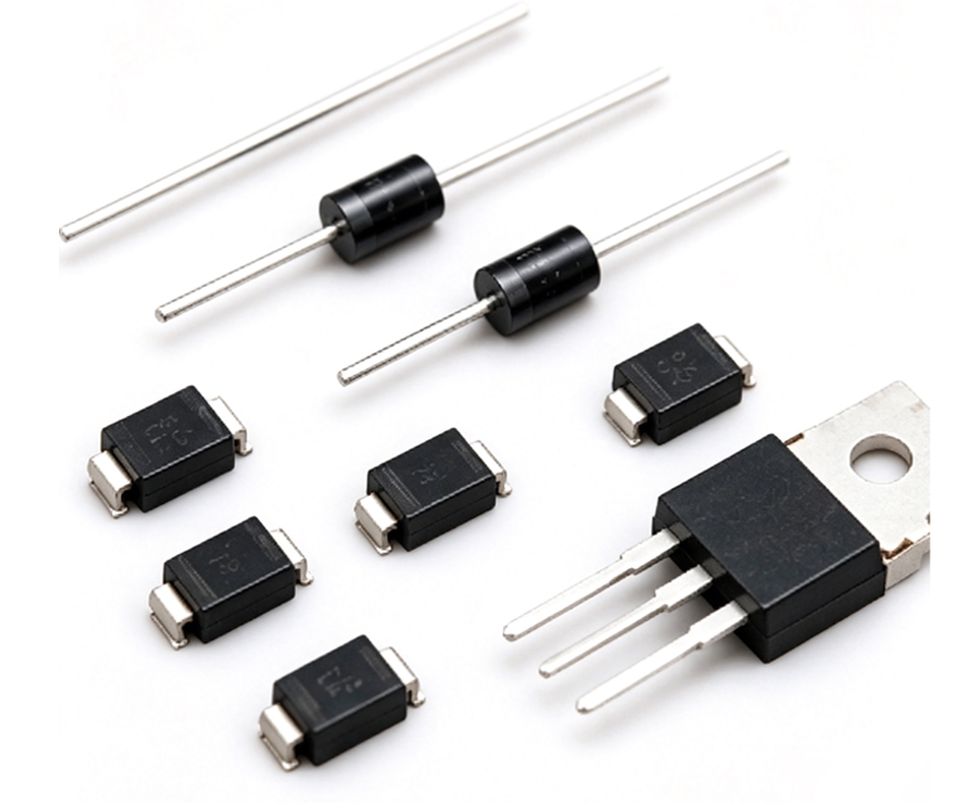
Below is a selection guide for reverse polarity protection diode:
1. Standard Silicon Rectifier Diode – Cost-Effective Universal Selection
- Core selection tips: Prioritize sufficient voltage and current margin, ignore minor power loss; select 1N4007 for 1A low-power circuits, 1N5408 for 3A high-power DC circuits.
- Applicable scenarios: Low-cost non-battery devices, fixed-power DC equipment, low-frequency static circuits with no strict efficiency requirements.
- Avoid usage: Low-voltage battery-powered products (serious voltage drop & power consumption), high-current long-working circuits.
2. Schottky Diode – First Choice for Low-Voltage & Battery Systems
- Core selection tips: Focus on low $$V_F$$ and temperature stability; choose low-leakage models for precision battery circuits, and high-surge models for automotive 12V systems.
- Applicable scenarios: 5V/12V low-voltage circuits, portable electronics, power banks, LED drivers, battery-powered wearable devices.
- Avoid usage: High-voltage industrial circuits (low reverse voltage tolerance), high-temperature extreme environments (aggravated leakage current).
- Recommended models: SS14/SS34 (universal), 1N5819 (industrial low-power).
3. Fast Recovery Diode – Dedicated for Switching & High-Frequency Circuits
- Core selection tips: Prioritize short reverse recovery time, match switching frequency of power supply; ensure surge current margin for frequent power-on/off scenarios.
- Applicable scenarios: Switching power supplies, high-frequency DC-DC modules, fast startup industrial control circuits.
- Avoid usage: Static low-frequency circuits (over-performance & cost waste), low-power portable devices.
4. Zener Diode – Auxiliary Protection Only, Not for Independent Use
- Core selection tips: Match Zener voltage with system rated voltage, configure matched current-limiting resistor; never use single Zener diode for reverse polarity blocking.
- Applicable scenarios: Circuits requiring dual reverse polarity protection + overvoltage clamping, low-precision industrial control modules.
- Avoid usage: High-current circuits (excessive power dissipation), pure reverse protection scenarios (low efficiency).
5. TVS Diode – Transient Surge Auxiliary Protection
- Core selection tips: Choose nanosecond-level fast response models, match system maximum withstand voltage; use as secondary protection, cooperate with series blocking diodes.
- Applicable scenarios: Automotive circuits, outdoor communication equipment, devices vulnerable to voltage transient spikes.
- Avoid usage: Independent reverse polarity protection (cannot block steady-state reverse voltage).
6. Selection Priority Rule (Quick Decision)
- Cost priority + low-frequency ordinary circuits → Standard Silicon Diode
- Battery power saving + low voltage + high efficiency → Schottky Diode
- High-frequency switching power circuits → Fast Recovery Diode
- Reverse protection + overvoltage dual protection → Zener + Rectifier Diode Combination
- Anti-surge + enhanced reliability → TVS + Main Protection Diode Combination
How to Use a Diode for Reverse Polarity Protection?
There are several practical ways to add reverse polarity protection into a PCB design.
- Use a Series Connection: Place the diode between the power source and the load. This is the simplest protection method and works well for low-current circuits.
- Use a Parallel Diode with Fuse: Connect the diode across the power rails together with a fuse. If the polarity is reversed, the diode conducts heavily and causes the fuse to disconnect the circuit.
- Select a Schottky Device for Low Voltage Systems: Schottky devices reduce voltage loss and improve power efficiency. They are commonly used in 5V and 12V circuits.
- Use MOSFET Protection for High Efficiency: MOSFET-based designs provide lower resistance and lower heat generation, making them suitable for high-current applications.
Reverse Polarity Protection Diode vs Mosfet: Which is Better?
Diode reverse polarity protection and MOSFET-based ideal diode protection are the two most mainstream power input protection solutions. Each has unique advantages in cost, efficiency, heat generation, and application scenarios. The following detailed comparison table helps designers quickly select the optimal scheme according to actual circuit needs.
| Comparison Dimension | Diode | MOSFET |
| Circuit Complexity | Extremely simple, only a single diode required, no peripheral circuits | Relatively complex, needs reasonable gate circuit design and layout optimization |
| Material & Production Cost | Ultra-low cost, widely universal and easy to purchase | Higher unit cost, requires precise device matching |
| On-State Voltage Drop | High (0.2~0.7V, varies by diode type) | Near zero millivolt drop, negligible loss |
| Power Efficiency | Moderate, obvious power loss under high current | Excellent, almost no invalid power consumption |
| Heat Generation | Obvious heat generation in long-term high-current operation | Minimal heat, no thermal pressure for continuous operation |
| PCB Space Occupation | Small package, saves board space | Moderate space occupation, needs thermal margin |
| High-Current Adaptability | Limited, easy to heat and degrade under large current | Excellent, supports high-current industrial and automotive loads |
| Battery System Adaptation | Average, voltage drop accelerates battery power consumption | Perfect, maximizes battery discharge efficiency and endurance |
| Applicable Scenarios | Low-current, low-cost, fixed-power, non-battery ordinary circuits | High-current, high-efficiency, battery-powered, automotive and industrial precision equipment |
In summary, diode protection is the preferred solution for cost-sensitive, low-demand ordinary circuits with simple deployment and stable performance. MOSFET-based ideal diode protection is more suitable for high-end, high-efficiency, battery-powered and high-current equipment, effectively solving the heat and power loss pain points of traditional diode protection.
Common Applications of Reverse Polarity Protection Diodes
Reverse voltage protection is widely used in many industries and electronic systems.
- Automotive Electronics: Used in car audio systems, ECU modules, lighting systems, and dashboard devices.
- Battery-Powered Products: Common in portable devices, battery chargers, and power banks.
- Industrial Equipment: Protects PLC systems, control boards, and industrial sensors.
- Communication Devices: Used in routers, RF modules, and wireless communication systems.
- LED Lighting Systems: Helps protect LED drivers and DC power input circuits.
How to Design a Reverse Polarity Protection Diode Circuit?
Designing a reliable reverse polarity protection circuit requires standardized parameter calculation, scheme selection, thermal optimization, and verification testing, balancing safety, power efficiency, cost, and long-term operational stability. The following step-by-step design workflow covers core engineering key points for diode and MOSFET protection schemes, suitable for all DC power input PCB designs.
Step 1: Confirm System Electrical Specifications & Working Conditions
Clarify the nominal DC input voltage, maximum peak voltage, steady-state operating current, instantaneous surge current, and working temperature range of the circuit in advance. Reserve sufficient margin for fluctuating power supply and transient spikes to avoid device breakdown or failure under abnormal working conditions.
Step 2: Complete Accurate Device Parameter Selection
Select protection devices strictly based on the quantified parameter rules above. Match forward current with 1.2~1.5 times the actual load current, and reverse blocking voltage with 1.5 times the maximum input voltage. Prioritize low VF Schottky diodes for battery and low-voltage high-efficiency circuits, and standard silicon diodes for cost-sensitive low-frequency circuits to avoid parameter mismatch leading to heat or burnout.
Step 3: Select the Optimal Protection Circuit Topology
Choose the circuit structure according to application scenarios: series single diode for simplest low-current low-cost equipment; parallel diode + fuse combination for high-surge industrial and automotive circuits to achieve fuse blowout protection under reverse short circuit; MOSFET ideal diode topology for high-current battery-powered products to eliminate voltage drop power loss.
Step 4: Conduct Thermal Calculation & Heat Dissipation Design
Calculate device power consumption based on operating current and forward voltage drop. For circuits with continuous current above 2A, reserve PCB copper area and thermal pads for heat dissipation. Avoid long-term overheating failure caused by excessive power loss of diodes, especially critical for high-current and closed industrial equipment.
Step 5: Standardize PCB Layout Optimization
Arrange the protection device close to the power input port to isolate reverse voltage at the first level. Adopt short and wide power traces to reduce line resistance and temperature rise. Separate power ground and signal ground properly to prevent reverse voltage interference from affecting sensitive small-signal circuits and improving overall anti-interference performance.
Step 6: Complete Abnormal Verification & Mass Production Testing
Perform strict reverse polarity connection test, long-term power-on aging test, and surge impact test before mass production. Verify no component damage, no abnormal heating, and normal circuit output after reverse connection. Eliminate hidden dangers of batch failure and ensure circuit stability in assembly, maintenance, and field use.
How to Choose a Reliable Reverse Polarity Protection Diode Supplier?
Selecting a reliable diode supplier is critical to guarantee consistent circuit protection performance, stable mass production, and low failure rates. The following practical, layered selection criteria cover quality, compliance, technology, delivery, and verification, balancing professionalism and practicability.
1. Compliance & Qualification Verification
Prioritize suppliers with complete standardized certifications. General consumer and industrial products require RoHS and REACH environmental compliance; industrial-grade suppliers need ISO9001 quality system certification; automotive electronic applications must pass IATF16949 and AEC-Q101 automotive-grade qualification to adapt to high-temperature and harsh working conditions.
2. Product Reliability & Test Data Support
Avoid selecting suppliers only by nominal parameters. Request official datasheets, third-party test reports, and long-term reliability test data, including HTRB high-temperature reverse bias test, surge current tolerance test, and high and low temperature cycle test. Focus on key indicators such as stable reverse leakage current and consistent forward voltage drop to prevent batch performance deviation.
3. Professional Technical Matching & Industry Experience
Choose suppliers with mature experience in your target application scenarios, including consumer electronics, automotive systems, industrial control, and communication equipment. Professional suppliers can provide targeted diode model recommendations, parameter margin guidance, and circuit layout suggestions to solve efficiency and heat dissipation problems in reverse polarity protection design.
4. Supply Stability & Delivery Capacity
Evaluate the supplier’s independent production capacity, wafer supply channels, and inventory reserve scale. Stable original wafer sources and complete production lines effectively avoid counterfeit devices and out-of-stock risks. Confirm fixed delivery cycles and flexible bulk order support to prevent production delays.
5. After-Sales & Customized Technical Support
Excellent suppliers provide complete after-sales services, including parameter verification, failure analysis, and technical debugging support. For special high-current, high-temperature, and high-frequency scenarios, prefer suppliers that support model customization and parameter optimization to meet personalized protection circuit requirements.
6. Sample Testing & Batch Verification
Always conduct sample testing before mass procurement. Verify key performance indicators such as reverse blocking stability, actual voltage drop, and heat generation under full load. Compare consistency between samples and official parameters to eliminate defective batches and ensure long-term operational reliability of reverse polarity protection circuits.
FAQs About Reverse Polarity Protection Diode
Q1: Do I really need reverse polarity protection diodes for low-voltage 5V/12V DC circuits?
A1: Yes, it is highly recommended. Low-voltage ICs, capacitors, and portable circuit components have extremely low reverse voltage tolerance. Even a momentary reverse connection during battery replacement or wiring can cause permanent burnout. A low-cost protection diode effectively eliminates human operation errors and improves circuit yield and durability.
Q2: What is the main downside of series diode reverse polarity protection?
A2: The core drawback is continuous forward voltage drop and power loss. Standard silicon diodes produce 0.6~0.7V voltage drop, while Schottky diodes produce 0.2~0.4V drop. Under high current loads, this causes obvious heat generation, reduces terminal voltage accuracy, and shortens battery endurance for portable devices.
Q3: Can Schottky diodes replace ordinary silicon diodes for all reverse protection scenarios?
A3: No. Schottky diodes feature low voltage drop and high efficiency, ideal for 5V/12V low-voltage battery systems. However, they suffer from higher reverse leakage current and lower reverse voltage resistance. They are not suitable for high-voltage industrial circuits or long-term high-temperature working environments, where silicon diodes are more stable.
Q4: Why is a single Zener diode unable to achieve reliable reverse polarity protection?
A4: Zener diodes are designed for voltage clamping and overvoltage protection instead of steady-state reverse blocking. A standalone Zener diode cannot completely cut off reverse current and will generate huge power dissipation under reverse bias, leading to overheating and burnout. It must cooperate with rectifier diodes for dual protection.
Q5: When should I choose MOSFET ideal diode protection over traditional diodes?
A5: Choose MOSFET solutions for high-current, battery-powered, and high-efficiency demanding scenarios. It achieves near-zero voltage drop with almost no heat loss, solving the power consumption and thermal problems of traditional diodes. For low-current, cost-sensitive ordinary circuits, traditional diodes remain more cost-effective.
Q6: What causes reverse protection diode failure in mass production?
A6: The main failure reasons include insufficient voltage/current parameter margin, excessive operating temperature leading to increased leakage current, unreasonable PCB layout causing poor heat dissipation, and untested surge current impact. Reasonable parameter derating and pre-production testing can effectively avoid batch failure.
Q7: What is the difference between series diode protection and parallel diode + fuse protection? A7: Series diode protection features simple wiring, no replacement cost, and suits low-current daily circuits. Parallel diode + fuse protection relies on short-circuit current to blow the fuse for isolation, offering stronger surge resistance, which is widely used in automotive and industrial high-power circuits.
Q8: Will reverse polarity protection diodes affect the normal operation and power supply accuracy of the circuit?
A8: Slight impact exists. Diodes produce fixed forward voltage drop, which slightly reduces the input voltage. For precision analog circuits and low-voltage battery systems, Schottky diodes or MOSFET protection are recommended to minimize voltage loss and ensure power supply stability and accuracy.
Conclusion
Reverse voltage accidents can seriously damage electronic products, especially in battery-powered and DC-powered systems. Choosing the right protection method helps improve reliability, thermal performance, and circuit safety.
Whether using a Schottky diode, standard rectifier diode, fuse-based protection, or MOSFET ideal diode design, proper selection and PCB layout are important for stable operation.
If you are looking for reliable PCBA manufacturing and circuit assembly support, welcome to contact us: sales@vn.danyupcbs.com. Our team provides professional PCBA solutions for industrial, automotive, communication, and power electronic products, including component sourcing, through-hole assembly service and so on.