 language
 english


How to Choose ESD Protection Diode?
How do you choose an ESD Protection Diode that protects sensitive signal lines without affecting normal circuit performance? An ESD protection diode gives transient current a controlled discharge path when static electricity enters through a connector, button, cable port, or exposed interface. When selected and placed correctly, it helps protect IC pins, communication lines, sensors, power inputs, and high-speed interfaces from electrostatic discharge.
This guide explains what an ESD protection diode is, how it works, which types are commonly used, which parameters matter, how to choose one, how to use it in an ESD protection diode circuit, how to test it, and how it differs from TVS diodes for ESD protection.
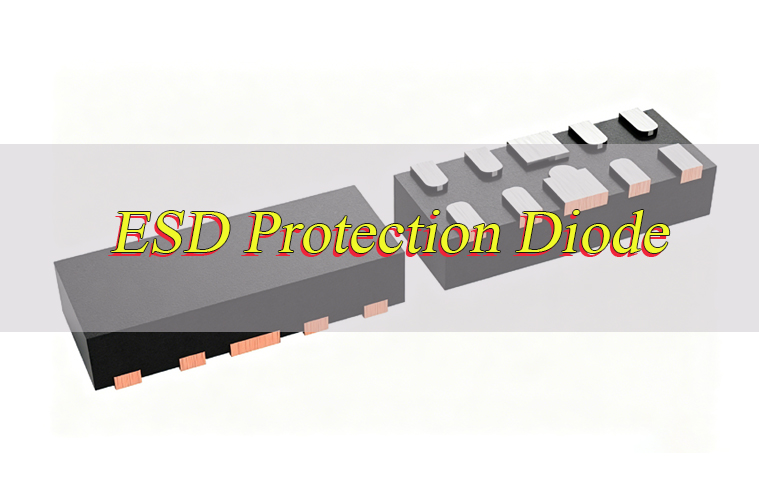
What is ESD Protection Diode?
An ESD protection diode is a semiconductor device used to protect electronic circuits from electrostatic discharge. ESD happens when static electricity suddenly transfers into a circuit, often through a connector, cable, button, or other exposed interface.
In normal operation, the ESD protection diode stays inactive. It should not affect the signal line, power rail, or communication interface. When an ESD pulse appears, the diode turns on quickly and diverts transient current away from the protected IC.
The main purpose of an ESD protection diode is to limit the voltage that reaches sensitive components. Modern IC pins can be damaged by fast high-voltage pulses, so an external protection diode helps create a safer discharge path before the transient energy reaches the device.
In PCB design, ESD protection diodes are usually placed close to the ESD entry point. Common examples include USB ports, CAN bus connectors, sensor inputs, buttons, display connectors, and other external signal interfaces.
How Does ESD Protection Diode Work?
The ESD protection diode working principle is based on fast response, current diversion, and voltage clamping. In simple terms, the diode stays quiet during normal operation and turns on only when the protected line sees an abnormal transient voltage. Its purpose is to conduct the unwanted surge current before the sensitive IC receives too much electrical stress.
- Normal circuit condition: The signal voltage stays within the normal working range. The ESD protection diode remains in a high-impedance state, so it has little influence on the protected line.
- ESD pulse arrival: A sudden transient voltage appears at the connector, button, cable port, or exposed pad. The voltage rises much faster than ordinary power noise or switching noise.
- Diode triggering: When the transient voltage exceeds the diode’s protection threshold, the diode starts to conduct.
- Current diversion: The ESD protection diode provides a lower-impedance path for the surge current. The current is guided toward ground, chassis, or a reference rail, depending on the circuit design.
- Voltage clamping: The diode limits the voltage on the protected line. This clamped voltage should be low enough to help protect the IC input, transceiver, sensor, or controller.
- Recovery after discharge: After the ESD event passes, the diode returns to its non-conducting state. The circuit continues normal operation.
- Role in signal protection: A good ESD diode protects the circuit without adding too much capacitance, leakage, or signal distortion.
- Role in PCB protection: The diode works best when placed close to the ESD entry point. A short discharge path helps reduce unwanted voltage spikes caused by trace inductance.
What Are Types of ESD Protection Diodes?
ESD protection diodes are not selected by name alone. The right type depends on the protected interface, normal voltage, signal speed, capacitance limit, clamping requirement, and PCB layout path. In real circuit design, engineers usually classify ESD protection diodes by channel count, polarity, capacitance, protected interface, and transient energy level.
- Single-Line ESD Protection Diodes
Single-line ESD protection diodes protect one signal or power line. They are often used for GPIO pins, reset lines, buttons, sensor inputs, low-speed digital signals, and simple external interfaces. This type is easy to place near the connector or exposed signal point. It is suitable when only one circuit node needs protection. - Multi-Channel ESD Protection Diode Arrays
ESD protection diode arrays integrate several protection channels into one small package. They are often used for USB, HDMI, Ethernet, SIM card connectors, display connectors, and multi-pin interfaces. Compared with placing several single-line parts, a diode array can save PCB space and simplify routing. However, engineers still need to check channel count, capacitance, pinout, package layout, and grounding path. - Unidirectional ESD Protection Diodes
Unidirectional ESD protection diodes are commonly used on DC power rails and signals that normally stay above ground. They provide strong clamping for transient events in one main direction. These parts are suitable for many low-voltage digital lines, power-related signals, and single-polarity circuits. The reverse working voltage should be higher than the maximum normal voltage of the protected line. - Bidirectional ESD Protection Diodes
Bidirectional ESD protection diodes are used when the signal may swing in both positive and negative directions. They are commonly found in CAN bus, RS485, audio lines, differential communication interfaces, and some industrial signal ports. For these lines, bidirectional clamping is usually more practical because the transient stress may appear in either polarity. - Low-Capacitance ESD Protection Diodes
Low-capacitance ESD protection diodes are designed for interfaces where signal quality matters. They are widely used on USB, HDMI, Ethernet, MIPI, DisplayPort, and other high-speed data lines. A diode with excessive capacitance can affect impedance, reduce signal margin, or cause data transmission errors. For this reason, capacitance is one of the first parameters to check for high-speed interfaces. - Ultra-Low-Capacitance ESD Protection Diodes for RF and Antenna Lines
RF and antenna circuits are more sensitive to parasitic capacitance than many digital interfaces. Even a small capacitance increase may affect matching, insertion loss, or wireless performance. For antenna ports, RF modules, and high-frequency signal paths, engineers usually choose ultra-low-capacitance ESD protection diodes with a package that supports short and clean routing. - Power-Line TVS Diodes for ESD and Surge Events
Power inputs, industrial terminals, automotive supply lines, and outdoor interfaces may face stronger transient energy than ordinary signal lines. In these cases, a larger TVS diode may be more suitable than a small signal-line ESD diode. These devices are selected for pulse power rating, surge current capability, clamping voltage, and thermal behavior. They may have higher capacitance, so they are not usually used on high-speed data lines. - Automotive-Grade ESD Protection Diodes
Automotive-grade ESD protection diodes are used in vehicle electronics, battery systems, lighting modules, sensors, infotainment systems, and communication networks. These parts are usually selected with attention to AEC-Q qualification, operating temperature range, long-term reliability, and stable supply. For CAN, LIN, and automotive sensor lines, both electrical performance and qualification grade should be reviewed. - Interface-Specific ESD Protection Devices
Some ESD protection devices are designed for specific interfaces such as USB Type-C, CAN bus, LIN bus, RS485, HDMI, Ethernet, SD card, and SIM card circuits. These parts often combine suitable capacitance, voltage rating, channel arrangement, and package layout for the target interface. They can make selection easier when the datasheet clearly matches the circuit requirement.
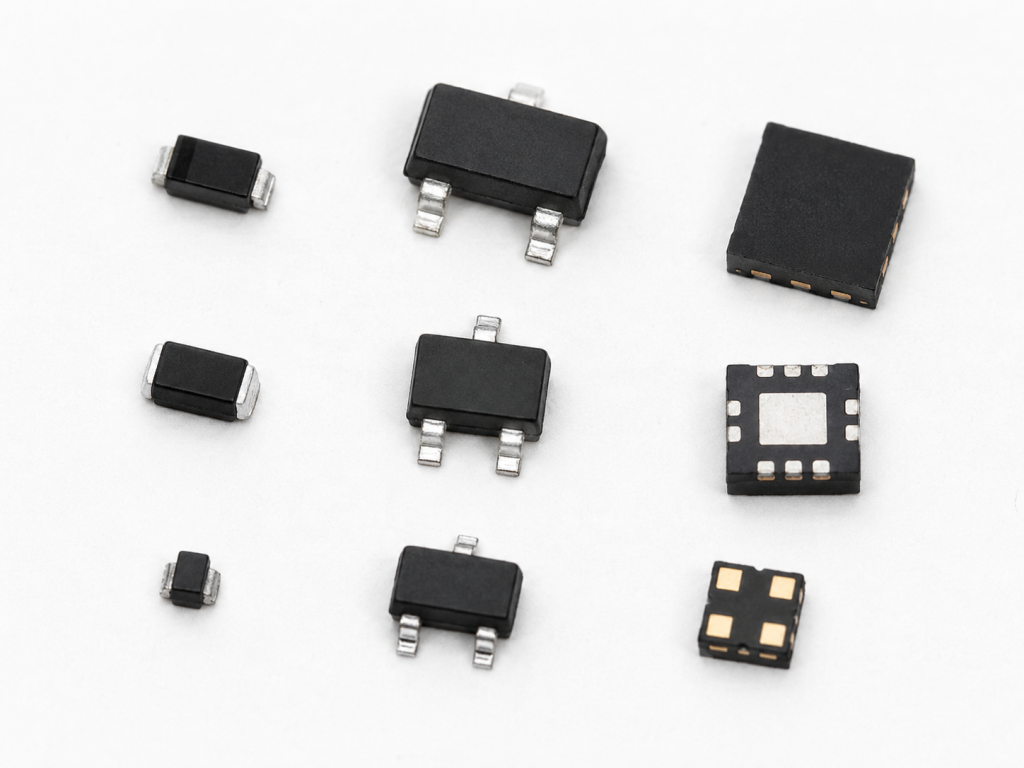
In short, the type of ESD protection diode should follow the circuit. For low-speed lines, a single-line or general-purpose ESD diode may be enough. For USB, HDMI, Ethernet, RF, and antenna circuits, capacitance becomes very important. For CAN bus and differential interfaces, bidirectional protection is often preferred. For power ports and harsher environments, a higher-power TVS diode may be the better choice.
What Are Parameters of ESD Protection Diodes?
The parameters of ESD protection diodes help engineers judge whether a device can protect the circuit while keeping the original signal stable. For example, USB data lines need very low capacitance, while power ports may need stronger pulse handling. The following table gives common value ranges used during early device screening.
| Parameter | Typical Value / Range |
|---|---|
| VRWM | 3.3 V, 5 V, 12 V, 24 V, 36 V |
| VBR | 5 V to 60 V |
| VC | 8 V to 100 V |
| CJ / CIO | 0.1 pF to 200 pF |
| IR | 1 nA to 10 uA |
| IPP | 1 A to 100 A |
| IEC 61000-4-2 Contact | +/-2 kV, +/-4 kV, +/-8 kV, +/-15 kV |
| IEC 61000-4-2 Air | +/-8 kV, +/-15 kV, +/-30 kV |
| RDYN | 0.1 ohm to 5 ohm |
| Channel Count | 1, 2, 4, 6, 8 |
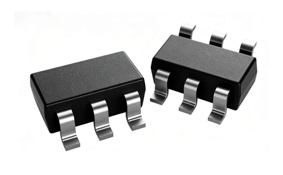
| Package | SOD-523, SOD-323, SOT-23, DFN, QFN, SOT-143 |
| Operating Temperature | -40 degC to +85 degC, -40 degC to +125 degC, -55 degC to +150 degC |
| AEC-Q Grade | AEC-Q101 |
| Capacitance for USB | 0.1 pF to 3 pF |
| Capacitance for CAN Bus | 10 pF to 100 pF |
| Power Rating | 100 W to 1500 W |
How to Choose ESD Protection Diode?
Choosing an ESD protection diode should start from the circuit condition, not from the smallest or cheapest package. A suitable device needs to stay inactive during normal operation, respond quickly during a discharge event, clamp voltage within a safer range, and avoid disturbing signal quality. For production use, availability and second-source planning also matter.
- Start with the protected interface
First, identify what line needs protection. A USB data line, CAN bus line, GPIO pin, RF antenna port, power input, and sensor input all have different electrical behavior. For example, USB and RF lines need very low capacitance, while power inputs usually need stronger surge handling. - Confirm the normal operating voltage
The reverse working voltage, usually marked as VRWM, should be higher than the maximum normal voltage on the line. If the protected line is 5 V, the diode should not start conducting during normal 5 V operation. If VRWM is too low, the circuit may suffer leakage, signal distortion, or unexpected loading. - Compare clamping voltage with IC tolerance
The clamping voltage shows how much voltage may remain on the line during a surge event. A lower clamping voltage usually gives better protection, but it must be reviewed together with working voltage and circuit behavior. The protected IC, MCU, transceiver, or sensor should not see a voltage higher than its safe transient limit. - Choose unidirectional or bidirectional structure
For DC power rails and one-direction digital signals, a unidirectional ESD protection diode is often suitable. For CAN bus, RS485, audio, differential lines, or signals that swing above and below ground, bidirectional ESD protection diodes are usually more practical. - Check capacitance for signal quality
Capacitance is very important on high-speed lines. A diode with too much capacitance can affect impedance, reduce eye margin, and cause communication problems. USB ESD protection diodes, HDMI protection parts, Ethernet protection arrays, and RF protection devices should use low-capacitance designs. - Review leakage current for sensitive circuits
Low leakage is useful for battery-powered products, medical electronics, sensor inputs, and precision analog circuits. If leakage is too high, it may affect measurement accuracy, standby current, or low-level signal stability. - Select the right channel count
A single-line device is suitable for one signal. An ESD protection diode array can protect several related lines in one package, which saves PCB space and simplifies routing. However, pin arrangement must match the PCB layout. - Match the package with PCB layout ability
Smaller packages reduce space and parasitic effects, but they also need better assembly control. For high-speed interfaces, the package should allow short routing, balanced differential pairs, and a clean discharge path to ground. - Review ESD rating carefully
Do not choose a device only because the datasheet shows a high kV rating. Check the test condition, contact discharge rating, air discharge rating, and waveform standard. A strong datasheet rating still needs correct PCB placement to work well in the final product. - Consider the real product environment
A handheld product, outdoor controller, automotive module, medical device, and industrial I/O board may face different discharge risks. Products with frequent cable plugging, human touch, or exposed metal parts usually need stronger ESD planning. - Check supply stability before production
A technically suitable diode should also be easy to source. For mass production, compare lead time, lifecycle status, authorized distributor stock, and similar replacement parts with the same package and pinout. - Use application-specific judgment
For USB, focus on low capacitance and clean differential routing. For CAN bus, focus on bidirectional protection and robust clamping. For RF, capacitance must be extremely low. For power inputs, a higher-power TVS diode may be more suitable than a tiny signal-line ESD diode.
How to Use ESD Protection Diode?
Using an ESD protection diode correctly depends on both circuit design and PCB layout. The diode must be placed where the discharge current can leave the board quickly, instead of traveling through the protected IC. A good schematic choice can still perform poorly if the PCB layout creates a long, inductive discharge path.
Step 1: Find the ESD entry point
Start with the areas where static discharge may enter the product. Common entry points include USB connectors, CAN terminals, buttons, exposed pads, sensor connectors, display ports, RF connectors, charging ports, and cable interfaces.
Step 2: Decide the protection structure
Use signal-to-ground protection for many single-ended lines. Use line-to-line or bidirectional protection for differential lines. Use an ESD protection diode array when several pins need protection in a compact area. For some interfaces, rail-to-rail protection may also be used, but the power rail behavior must be reviewed carefully.
Step 3: Place the diode near the connector
The diode should be close to the connector or exposed interface. The goal is to intercept the ESD current before it moves deeper into the PCB. If the diode is placed near the IC instead of the connector, the discharge current may pass through a long trace and create extra voltage stress.
Step 4: Route the signal through the protection area
The signal path should pass through or next to the ESD protection device before reaching the protected IC. Avoid placing the diode on a long side branch. A long branch adds inductance and can reduce the protection effect, especially during fast ESD pulses.
Step 5: Build a short ground return path
The ground connection should be short, wide, and direct. If possible, connect the diode ground pin to a solid ground plane through one or more nearby vias. A long or narrow ground path can increase voltage overshoot during discharge.
Step 6: Keep high-speed routing clean
For USB, HDMI, Ethernet, RF, and other high-speed interfaces, keep trace length short and maintain impedance control. Avoid sharp discontinuities, long stubs, and unbalanced routing between differential pairs. The ESD protection diode should protect the line without becoming a signal-quality problem.
Step 7: Review chassis ground and signal ground strategy
In some products, ESD current may be guided to chassis ground rather than directly into the signal ground plane. The best grounding method depends on enclosure design, connector structure, shielding, and EMC requirements. This decision should be reviewed during system-level design.
Step 8: Confirm the diode orientation and pinout
Always check the datasheet pin configuration before layout and assembly. ESD protection diode arrays may look similar from the outside, but their internal structures can be different. Wrong orientation can leave the interface unprotected.
Step 9: Avoid routing sensitive traces under the discharge path
ESD current is fast and noisy. Keep sensitive analog lines, clock traces, reset lines, and precision sensor paths away from the main discharge route when possible.
Step 10: Review the complete ESD protection diode circuit
After layout, check whether the discharge current has a direct path to ground or chassis. The path should not pass through the IC, narrow traces, long loops, or fragile signal routing.
Step 11: Validate the design on the real PCB
Final protection depends on the diode, connector, routing, ground plane, enclosure, cable, and IC tolerance. A design that looks correct in the schematic should still be verified during prototype testing.
How to Test ESD Protection Diode?
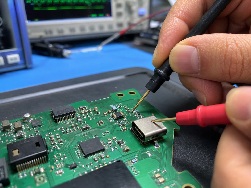
Testing an ESD protection diode should be divided into two levels: component-level checking and system-level validation. A multimeter can help find obvious short or open failures, but it cannot prove that the diode will protect a circuit under a real ESD pulse. For reliable results, engineers should combine visual inspection, electrical measurement, signal testing, and product-level ESD testing.
Step 1: Check package marking and orientation
Confirm the part marking, package type, polarity, and placement direction. This is especially important for small SMD devices and diode arrays, because wrong orientation may not be easy to see after assembly.
Step 2: Inspect soldering quality
Look for solder bridges, open joints, tombstoning, package cracks, pad lifting, or contamination. A diode with poor soldering may pass a simple electrical check but fail during a real discharge event.
Step 3: Use a multimeter for basic diode-mode testing
Diode mode can help detect obvious short circuits or open circuits. For bidirectional devices and diode arrays, readings may vary depending on internal structure, so compare the result with a known good sample or datasheet guidance.
Step 4: Measure leakage current
Apply the specified reverse working voltage and measure leakage current. Excessive leakage may indicate component damage, wrong part selection, or soldering contamination. This test is useful for battery-powered products and sensor circuits.
Step 5: Measure capacitance when signal speed matters
For USB ESD protection diodes, RF lines, HDMI, Ethernet, and other high-speed interfaces, capacitance should be verified when there is concern about signal quality. A wrong replacement part with higher capacitance may pass basic continuity testing but cause communication failure.
Step 6: Use a curve tracer for breakdown behavior
A curve tracer can show whether the diode begins conducting at the expected voltage range. This helps identify abnormal breakdown behavior, damaged parts, or incorrect component substitutions.
Step 7: Test the protected interface during normal operation
Before applying ESD stress, confirm that the interface works normally. For example, check USB data transfer, CAN bus communication, Ethernet link stability, RF performance, sensor readings, or GPIO response. This helps separate normal design issues from ESD-related failure.
Step 8: Perform system-level ESD testing
Use ESD gun testing on the complete product or PCB assembly. Apply contact discharge and air discharge according to the product requirement. Test points should include connectors, buttons, ports, exposed metal areas, cable shields, and other user-accessible surfaces.
Step 9: Start from lower stress levels
During validation, it is safer to begin from lower discharge voltage and increase gradually according to the test plan. This helps identify weak points before severe damage occurs.
Step 10: Monitor the product during and after discharge
Check whether the device resets, freezes, loses communication, shows abnormal readings, or suffers permanent damage. A product may survive physically but still fail functional performance during ESD events.
Step 11: Compare electrical behavior before and after testing
After ESD testing, measure the protected line again. Check leakage current, communication stability, signal waveform, and power rail behavior. Some diodes may become partially damaged and show increased leakage after repeated stress.
Step 12: Analyze failure by reviewing the whole discharge path
If the product fails, do not blame only the diode. Review connector design, ground path, diode placement, trace length, enclosure grounding, cable shielding, and IC tolerance. Many ESD failures are caused by layout path problems rather than the protection diode itself.
Step 13: Record test results for future production
Keep part number, test voltage, discharge location, failure mode, waveform observation, and corrective action records. These records help engineering, purchasing, and quality teams manage future revisions or replacement parts.
Differences Between ESD Protection Diodes and TVS Diodes
ESD protection diodes and TVS diodes are closely related, but their use cases are not always the same. Many ESD protection diodes belong to the TVS family, yet engineers often use “ESD protection diode” to describe compact devices for signal and interface protection. General TVS diodes may be used for stronger transient events, especially on power inputs and industrial ports.
| Item | ESD Protection Diodes | TVS Diodes |
|---|---|---|
| Main Purpose | Interface-level ESD protection | Transient voltage suppression |
| Typical Use | USB, CAN bus, HDMI, GPIO, RF, sensors | Power rails, industrial ports, automotive lines, surge inputs |
| Capacitance | Usually low or ultra-low | Low to high |
| Package Size | Often compact | Small to large |
| Surge Capability | Designed for ESD pulse protection | Often supports higher surge energy |
| Signal Impact | Designed for signal-line use | Depends on capacitance and device type |
| Common Structure | Single-line, bidirectional, diode array | Unidirectional, bidirectional, high-power TVS |
| Selection Focus | VRWM, VC, capacitance, leakage, IEC ESD rating | VRWM, VC, power rating, surge current |
| High-Speed Suitability | Common for USB, HDMI, RF, Ethernet | Suitable only when capacitance is low enough |
| Power-Line Suitability | Limited by package and surge rating | Often stronger for power ports |
| Circuit Placement | Close to connector or exposed interface | Close to surge entry point |
| Typical Design Goal | Protect IC pins with low signal loading | Clamp higher-energy transient events |
What Are Applications of ESD Protection Diodes?
ESD protection diodes are used wherever static discharge may enter a product through a user-facing or cable-facing interface. The application range is broad because almost every modern electronic product has exposed pins, ports, or contact points. The protection part should be chosen according to the interface speed, voltage range, discharge risk, and product environment.
- USB ports: USB ESD protection diodes protect D+, D-, SuperSpeed pairs, ID pins, CC pins, and VBUS-related areas.
- CAN bus interfaces: CAN bus ESD protection diode designs often use bidirectional protection across CAN_H and CAN_L.
- HDMI and DisplayPort interfaces: Low-capacitance diode arrays help protect high-speed video lines.
- Ethernet ports: ESD protection devices help protect data lines from cable-side discharge.
- RF and antenna circuits: Ultra-low-capacitance devices protect antenna ports while preserving RF performance.
- GPIO lines: Simple single-line ESD protection diodes can protect exposed digital pins.
- Buttons and input panels: Human-touch interfaces often need protection against repeated static discharge.
- Sensor inputs: Low-leakage ESD diodes help protect analog and digital sensor lines.
- Battery charging ports: Charging connectors can use ESD and transient protection around power and data pins.
- Industrial control boards: PLCs, motor drives, control modules, and I/O boards often need protection at external terminals.
- Automotive electronics: ESD protection is used in infotainment, lighting, battery systems, body control modules, sensors, and communication networks.
- Medical electronics: Patient-facing and operator-facing interfaces may require stable ESD protection design.
- IoT devices: Wireless modules, charging ports, buttons, and sensor interfaces often use compact ESD diodes.
Which Companies Supply High Performance ESD Protection Diodes?
Many semiconductor manufacturers supply high performance ESD protection diodes, but the best choice depends on the circuit instead of brand name alone. Engineers should compare electrical ratings, capacitance, package, qualification level, stock status, and reference design support. For purchasing teams, long-term availability and alternate sourcing are also important during mass production.
- Texas Instruments: Supplies ESD protection devices for USB, HDMI, Ethernet, automotive, industrial, and general interface protection.
- STMicroelectronics: Provides ESD protection, EMI filtering, and low-capacitance protection devices for high-speed interfaces.
- Nexperia: Offers a wide ESD protection portfolio, including low-capacitance parts, diode arrays, and automotive-grade devices.
- Littelfuse: Known for circuit protection products, including TVS diodes and ESD protection solutions.
- onsemi: Supplies ESD protection devices for consumer, industrial, communication, and automotive circuits.
- Vishay: Provides TVS diodes, ESD protection diodes, and discrete semiconductor protection components.
- Semtech: Offers protection solutions for communication interfaces, high-speed lines, and sensitive electronic systems.
- Toshiba: Supplies ESD protection diodes and TVS diodes for signal and power protection.
- Infineon: Provides protection components for industrial, automotive, and power-related applications.
- ROHM: Offers ESD protection devices, TVS diodes, and discrete semiconductor components.
- Diodes Incorporated: Supplies ESD protection arrays, TVS devices, and discrete protection products.
- Bourns: Provides circuit protection products for surge, ESD, and transient voltage events.
FAQs About ESD Protection Diodes
Q1: Can a normal diode be used for ESD protection?
A1: A normal diode can provide limited clamping in very simple circuits, but it is not recommended as the main ESD protection device. Dedicated ESD protection diodes are designed for fast response, controlled clamping, low leakage, and tested transient performance.
Q2: What does an ESD protection diode symbol show in a schematic?
A2: An ESD protection diode symbol may show a TVS-style diode, Zener-style diode, bidirectional diode, or diode array. The symbol helps show the protection concept, but the final layout should always follow the datasheet pinout and internal structure.
Q3: When does back to back diode ESD protection make sense?
A3: Back to back diode ESD protection is related to bidirectional clamping. It makes sense when the protected signal can move in both positive and negative directions. Engineers should still confirm working voltage, clamping voltage, capacitance, and ESD rating from the datasheet.
Q4: Why do USB ESD protection diodes need low capacitance?
A4: USB lines carry high-speed signals, so added capacitance can affect impedance and signal quality. Low-capacitance USB ESD protection diodes help protect the port while reducing the risk of eye diagram degradation, data errors, or unstable communication.
Q5: Should a CAN bus use bidirectional ESD protection diodes?
A5: Yes, CAN bus commonly uses bidirectional ESD protection diodes because CAN_H and CAN_L operate as a differential pair and may experience transient stress in both directions. For automotive or industrial CAN designs, temperature range and qualification grade should also be reviewed.
Q6: Can one ESD protection diode array protect multiple signal lines?
A6: Yes. An ESD protection diode array can protect several signal lines in one compact package. It is commonly used for USB, HDMI, Ethernet, SIM card, display connector, and other multi-line interfaces. The array should match the channel count, capacitance limit, pinout, and routing direction.
Q7: How close should an ESD diode be to the connector?
A7: It should be placed as close as possible to the connector or ESD entry point. A short distance gives transient current a faster discharge path and reduces the chance that the surge travels deeper into the PCB.
Q8: What happens if the clamping voltage is too high?
A8: The protected IC may still see excessive voltage during an ESD event. The diode may conduct, but the remaining voltage may still exceed the safe limit of the IC. This can lead to reset, leakage increase, communication failure, or permanent damage.
Q9: How can I check whether an ESD diode is damaged?
A9: Start with visual inspection and diode-mode testing. Then check for shorts, opens, abnormal leakage current, and communication problems on the protected line. For deeper analysis, capacitance measurement, curve tracing, or system-level ESD testing may be needed.
Q10: Does every connector need ESD protection?
A10: Not every connector needs the same protection level, but any connector exposed to users, cables, service tools, or harsh environments should be reviewed. USB, CAN bus, HDMI, Ethernet, buttons, charging ports, and sensor inputs are common protection points.
Q11: Are TVS diodes for ESD protection suitable for high-speed signal lines?
A11: Some TVS diodes are suitable for high-speed lines, but only when their capacitance is low enough for the interface. Larger TVS diodes with higher capacitance may work well on power lines, but they can disturb USB, HDMI, Ethernet, RF, or other fast signals.
Q12: What should be checked before replacing one ESD diode with another?
A12: Check package, pinout, VRWM, clamping voltage, capacitance, leakage current, channel count, ESD rating, temperature range, and qualification grade. For high-speed interfaces, capacitance and PCB footprint should be reviewed carefully before substitution.
Conclusion
Choosing an ESD protection diode requires more than matching a voltage number. A strong selection should consider the protected interface, working voltage, clamping voltage, capacitance, leakage current, package, PCB placement, ESD rating, and long-term supply stability.
For USB ESD protection diodes, capacitance and routing quality are critical. For CAN bus ESD protection diode selection, bidirectional behavior and robust clamping are important. For multi-line interfaces, an ESD protection diode array can simplify design and save PCB space.
When the diode is selected correctly and placed close to the ESD entry point, it helps the circuit survive real-world handling, cable connection, static discharge, and field operation with better reliability.