 language
Electron Devices and Circuits for PCB Design and Assembly
Electron devices and circuits is a commonly searched term used to describe how electronic components work together inside an electrical system. In practical engineering, the more standard term is electronic devices and circuits, which refers to semiconductor devices, passive components, integrated circuits, and the circuit structures that connect them.
For PCB designers, hardware engineers, and product developers, this topic is more than basic theory. It affects component selection, schematic design, PCB layout, signal integrity, power stability, manufacturability, and final product reliability. This guide explains the basics of electron devices and circuits, then connects them with real PCB design and assembly applications.
What Are Electron Devices and Circuits (Electronic Devices and Circuits)?
Electron devices and circuits is a commonly searched term used to describe how electronic components work together within a system. In engineering practice, the more accurate term is electronic devices and circuits, which refers to the combination of semiconductor devices, passive components, and circuit structures that control electrical signals and power.
In simple terms:
- Electronic devices include components such as resistors, capacitors, diodes, transistors, and integrated circuits
- Circuits are the conductive paths that connect these devices to perform specific functions
- PCB design transforms these circuits into a physical, manufacturable product
Although “electron devices and circuits” is widely used in search queries, engineers typically use “electronic devices and circuits” to describe real-world applications. Both terms generally refer to the same concept: electronic components working together through designed circuits to process signals, manage power, and enable system functionality.
Best Technology specializes in turning electron devices and circuits from schematic concepts into reliable PCB and PCBA products, supporting engineers from component selection, PCB layout review, DFM analysis, assembly, inspection, to final testing. With strong experience in passive components, semiconductor devices, ICs, power circuits, analog/digital circuits, and mixed-signal systems, we help customers improve circuit stability, signal integrity, thermal performance, and manufacturability. From prototypes to high-reliability applications such as industrial electronics, medical devices, automotive electronics, RF modules, and power electronics, Best Technology provides one-stop PCB fabrication and assembly solutions with engineering support, quality control, and practical production expertise. If you have any new projects needed us to help, a warm welcome to contact us via sales@vn.danyupcbs.com.
What Are the Basic Electronic Devices Used in Circuits?
Electronic circuits are built from several common devices. Each component has its own function, and good circuit design depends on using them correctly.
Resistor
A resistor limits current, divides voltage, and sets bias conditions in a circuit. It is one of the most common passive components on a PCB.
Typical uses include:
- Current limiting for LEDs
- Pull-up and pull-down circuits
- Voltage divider networks
- Signal conditioning
- Transistor biasing
For example, when an LED is connected to a 5V supply, a resistor is usually added in series to prevent excessive current. Without proper current control, the LED may run outside its safe working range.
Capacitor
A capacitor stores and releases electrical energy. In PCB design, capacitors are widely used for filtering, decoupling, timing, and energy buffering.
Typical uses include:
- Power supply filtering
- Noise reduction
- Signal coupling
- Timing circuits
- Voltage stabilization near IC pins
In digital circuits, decoupling capacitors are often placed close to IC power pins. This helps provide local energy during fast switching and improves power integrity.
Diode
A diode allows current to flow mainly in one direction. It is often used for protection, rectification, and signal control.
Typical uses include:
- Reverse polarity protection
- Rectifier circuits
- Flyback protection
- Voltage clamping
- Signal shaping
In relay or motor control circuits, a flyback diode can protect other components from voltage spikes caused by inductive loads.
Transistor
A transistor can work as a switch or amplifier. It is essential in digital switching, analog amplification, and power control.
Typical uses include:
- Driving LEDs, relays, and motors
- Amplifying weak signals
- Switching loads
- Power regulation
- Logic control
For example, a microcontroller output pin may not provide enough current to drive a relay directly. A transistor can act as a controlled switch between the microcontroller and the relay.
Integrated Circuit
An integrated circuit, or IC, combines many internal components into one package. ICs make modern electronics compact, powerful, and efficient.
Common IC types include:
- Microcontrollers
- Voltage regulators
- Operational amplifiers
- Motor drivers
- Communication chips
- Memory devices
- Power management ICs
In real PCB assembly, IC package type, pin pitch, thermal pad design, and soldering process all affect final reliability.
How Do Electronic Circuits Work?
Electronic circuits work by controlling voltage, current, and signal flow through connected components. Each component affects the electrical behavior of the circuit.
A simple circuit usually has three basic parts:
- Power source
- Conductive path
- Load or functional device
More advanced circuits may include sensors, processors, filters, regulators, protection devices, and communication interfaces.
Signal Flow
Signal flow describes how information travels through a circuit. In an audio amplifier, a small input signal is processed and amplified into a stronger output signal. In a sensor board, a physical value such as temperature or pressure is converted into an electrical signal.
Good PCB layout helps preserve signal quality. Poor routing, long return paths, or excessive noise coupling can reduce circuit performance.
Power Flow
Power flow describes how energy is delivered to the circuit. Stable power is essential for reliable operation.
A power circuit may include:
- Input protection
- Voltage regulator
- Bulk capacitors
- Decoupling capacitors
- Power planes
- Thermal vias
When power distribution is designed properly, ICs receive stable voltage and the product works more consistently.
Control Logic
Control logic allows circuits to make decisions. A microcontroller may read sensor data, process the information, and control outputs such as motors, LEDs, or communication modules.
This is where electronic devices and circuits become part of a larger electronic system.
What Is the Difference Between Electric Circuits and Electronic Devices?
The phrase electric circuits and electronic devices often appears together, but the two ideas are not exactly the same.
An electric circuit focuses mainly on the path of electrical energy. It may include a power source, wires, switches, and loads. An electronic device usually performs a more specific control, conversion, switching, or signal-processing function.
| Item | Electric Circuits | Electronic Devices |
|---|---|---|
| Main focus | Energy transfer | Signal or power control |
| Typical parts | Wires, switches, loads | Diodes, transistors, ICs |
| Function | Deliver electricity | Process or control electricity |
| Example | Lamp circuit | Sensor control board |
| PCB relevance | Basic routing | Full system design |
In modern products, both are connected. A PCB must support electric current paths while also allowing electronic devices to perform accurate control.
How Are Electron Devices and Circuits Used in PCB Design?
Electron devices and circuits become practical when they are placed onto a PCB. The PCB is the physical platform that connects components, supports mechanical structure, and controls electrical performance.
A schematic shows the logical circuit. A PCB layout turns that schematic into copper traces, pads, vias, planes, and solderable component footprints.
Component Placement
Good component placement improves signal flow, thermal behavior, and assembly efficiency.
Engineers usually place:
- Power components near power input areas
- Decoupling capacitors close to IC power pins
- Sensitive analog circuits away from noisy switching circuits
- Connectors in positions that match enclosure design
- Heat-generating parts near copper areas or thermal paths
Placement is not only about fitting components on the board. It directly affects circuit stability and manufacturing yield.
Trace Routing
Copper traces carry current and signals between devices. Trace width, spacing, length, and layer assignment all matter.
For example:
- High-current traces need wider copper paths.
- High-speed traces may require impedance control.
- Sensitive signals need clean return paths.
- Power traces should avoid unnecessary voltage drop.
A circuit may look correct in the schematic, but poor routing can still cause noise, heating, or unstable operation.
Power Integrity
Power integrity means the circuit receives stable and clean power. It is especially important for microcontrollers, RF modules, processors, and precision analog circuits.
A good power design may include:
- Proper voltage regulator selection
- Bulk capacitors near input power
- Decoupling capacitors near ICs
- Low-impedance power and ground planes
- Short current loops
Stable power helps electronic devices perform as intended.
Signal Integrity
Signal integrity becomes important when circuits handle fast edges, high frequencies, or sensitive analog signals.
Common design concerns include:
- Crosstalk
- Reflection
- EMI
- Ground bounce
- Return path discontinuity
- Impedance mismatch
For RF, high-speed digital, or precision measurement circuits, PCB layout becomes part of the circuit itself.
Thermal Management
Many electronic devices generate heat. If heat is not handled properly, performance and lifespan may be affected.
PCB-level thermal solutions include:
- Wider copper areas
- Thermal vias
- Thicker copper
- Metal-core PCB
- Heat sink connection
- Proper component spacing
For power electronics, LED modules, automotive boards, and industrial controllers, thermal design is a major engineering requirement.
Why Do Electronic Devices and Circuits Matter in PCB Assembly?
PCB assembly turns designed circuits into physical electronic products. At this stage, component quality, soldering accuracy, inspection, and process control become very important.
Even a well-designed circuit can perform poorly if assembly quality is inconsistent.
Component Package Selection
Different electronic devices come in different package types, such as:
- SMD resistors and capacitors
- SOT packages
- QFN packages
- BGA packages
- DIP packages
- Connectors
- Power modules
Smaller packages save space, but they also require better process control. Fine-pitch ICs, BGAs, and QFNs need accurate placement, solder paste control, and inspection.
Soldering Quality
Solder joints create the electrical and mechanical connection between components and PCB pads.
Good soldering supports:
- Stable electrical contact
- Long-term mechanical strength
- Better thermal transfer
- Lower failure risk
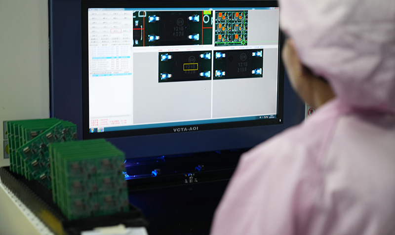
For complex PCB assembly, AOI, X-ray inspection, and functional testing can help verify quality.
DFM Review
DFM means Design for Manufacturability. It helps identify issues before production.
A useful DFM review may check:
- Pad design
- Component spacing
- Solder mask clearance
- Drill size
- Copper spacing
- Panelization
- Assembly direction
- Test point access
This step is valuable because it reduces production risk before the board enters mass manufacturing.
What Are Common Applications of Electronic Devices and Circuits?
Electronic devices and circuits are used across almost every industry. The exact design requirements depend on the final application.
Consumer Electronics
Consumer products need compact design, stable performance, and cost-efficient production.
Examples include:
- Smart home devices
- Wearable electronics
- Audio products
- Chargers
- Remote controllers
These products often require compact PCB layouts and reliable SMT assembly.
Industrial Electronics
Industrial equipment focuses on durability, noise immunity, and long-term operation.
Examples include:
- Motor controllers
- PLC modules
- Power control boards
- Sensor interfaces
- Automation equipment
Industrial circuits often need strong protection against surge, vibration, heat, and electrical noise.
Medical Electronics
Medical electronic devices require high reliability, stable performance, and strict quality control.
Examples include:
- Monitoring equipment
- Diagnostic devices
- Portable medical instruments
- Sensor modules
- Control boards
For these applications, PCB manufacturing and assembly should support traceability, documentation, and consistent process control.
Automotive Electronics
Automotive circuits operate in demanding environments with temperature changes, vibration, and electrical stress.
Examples include:
- Lighting control modules
- Battery management systems
- Sensor boards
- Power control units
- Infotainment electronics
Automotive PCB projects often need careful material selection, thermal design, and robust assembly processes.
Communication and RF Systems
RF and communication circuits require precise signal behavior.
Examples include:
- Antenna boards
- Wireless modules
- RF front-end circuits
- IoT communication boards
- Microwave systems
For these circuits, PCB material, impedance control, stack-up design, and manufacturing tolerance are especially important.
How to Design Electronic Systems with Circuits and Devices?
Designing electronic systems with circuits and devices requires a structured workflow. A reliable product is not created by schematic design alone.
Step 1: Define System Requirements
Start by clarifying voltage, current, signal type, operating environment, size limits, and reliability expectations.
Key questions include:
- What voltage does the circuit need?
- How much current will it draw?
- Is the signal analog, digital, RF, or power?
- What temperature range must it support?
- Will the product face vibration or humidity?
- Does it need certification or industry compliance?
Clear requirements help engineers choose suitable components and PCB structures.
Step 2: Select the Right Electronic Devices
Component selection affects cost, performance, availability, and manufacturability.
Engineers should consider:
- Electrical rating
- Package type
- Tolerance
- Temperature range
- Lifecycle status
- Supplier availability
- Assembly difficulty
A component may perform well on paper, but it also needs to fit the production process.
Step 3: Build the Schematic
The schematic defines how devices connect electrically. It should include proper power input, protection, filtering, signal paths, and test points.
A good schematic is clear, organized, and easy to review.
Step 4: Convert the Circuit into PCB Layout
PCB layout determines how the circuit behaves physically. This is where routing, layer stack-up, ground design, and thermal paths are created.
For complex boards, engineers may need:
- Multilayer PCB
- Controlled impedance
- HDI structure
- Blind or buried vias
- High-Tg material
- Heavy copper
- Metal-core PCB
- RF laminate
Step 5: Prototype and Test
Prototype testing confirms whether the design works in real conditions.
Common tests include:
- Visual inspection
- Electrical test
- Functional test
- Power-on test
- Signal measurement
- Thermal test
- Aging test
Testing helps engineers improve the design before mass production.
What PCB Manufacturing Factors Affect Circuit Performance?
PCB manufacturing has a direct influence on electronic circuit performance. A circuit is not only defined by schematic values; it is also shaped by physical material and production tolerance.
Copper Thickness
Copper thickness affects current capacity, voltage drop, heat dissipation, and mechanical strength. Power circuits often need thicker copper than low-current signal circuits.
Trace Width and Spacing
Trace width determines current-carrying ability. Spacing affects insulation, safety, and manufacturability.
Fine-pitch circuits require precise etching and stable process control.
Material Selection
PCB material affects thermal behavior, dielectric performance, mechanical strength, and high-frequency loss.
Common material choices include:
- FR4
- High-Tg FR4
- Rogers laminate
- Aluminum substrate
- Copper core PCB
- Ceramic substrate
- Flexible materials
For high-frequency or high-power circuits, material selection becomes a major design decision.
Layer Stack-Up
Multilayer PCBs provide better routing density, power distribution, EMI control, and signal return paths.
A typical multilayer PCB may include:
- Signal layers
- Ground planes
- Power planes
- Controlled impedance layers
A well-designed stack-up can improve both electrical performance and manufacturing stability.
Surface Finish
Surface finish protects exposed copper and supports soldering.
Common options include:
- HASL
- ENIG
- OSP
- Immersion silver
- Immersion tin
- Hard gold
The right choice depends on component type, soldering process, shelf life, and application requirements.
How Can One-Stop PCB Assembly Support Electronic Devices and Circuits?
For real engineering projects, one-stop PCB assembly can make development smoother. Instead of separating PCB fabrication, component sourcing, assembly, and testing, a one-stop supplier manages the complete chain.
This is useful when the project includes many electronic devices, tight layout constraints, or strict reliability requirements.
A capable one-stop PCBA partner can support:
- PCB fabrication
- Component sourcing
- BOM review
- DFM analysis
- SMT assembly
- DIP assembly
- IC programming
- AOI inspection
- X-ray inspection
- Functional testing
- Box-build assembly
For engineers, this reduces communication gaps and helps solve problems earlier.
At EBest, our engineering support focuses on practical manufacturability. We help customers review PCB files, optimize BOM choices, and manage assembly details from prototype to production. This is especially valuable for multilayer boards, high-frequency PCBs, medical electronics, automotive electronics, industrial controllers, and other reliability-sensitive applications.
What Should Engineers Check Before Sending a Circuit Design for PCB Production?
Before sending files to a PCB manufacturer, engineers should review both electrical design and manufacturing details.
Recommended Checklist
| Item | What to Check | Why It Matters |
|---|---|---|
| Schematic | Power, ground, signal connections | Prevents functional errors |
| BOM | Part number, package, lifecycle | Reduces sourcing risk |
| Footprints | Pad size and pin mapping | Avoids assembly mismatch |
| Trace width | Current capacity | Improves safety and reliability |
| Clearance | Voltage and manufacturing limits | Supports stable production |
| Stack-up | Layer structure and impedance | Improves signal performance |
| Thermal design | Heat path and copper area | Protects components |
| Test points | Access for testing | Makes debugging easier |
| DFM | Manufacturing compatibility | Reduces production issues |
This checklist helps connect electronic devices and circuits with real PCB manufacturing requirements.
In conclusion, electron devices and circuits may sound like a basic topic, but in real engineering it connects directly with PCB design, component selection, assembly quality, and product reliability. The more accurate term, electronic devices and circuits, describes the practical foundation behind almost every modern electronic product.
For engineers, the real challenge is not only understanding each component. It is knowing how those devices behave together on a physical PCB.
A reliable product depends on the full chain:
Component selection → Circuit design → PCB layout → Manufacturing → Assembly → Testing
When these stages are managed together, electronic systems become more stable, manufacturable, and ready for real-world applications. For PCB fabrication, PCBA assembly, BOM review, DFM support, and one-stop electronic manufacturing service, feel free to contact Best Technology at sales@vn.danyupcbs.com.
FAQs About Electron Devices and Circuits
What does electron devices and circuits mean?
Electron devices and circuits is a search phrase used to describe electronic components and the circuits they form. In professional engineering, the more accurate term is electronic devices and circuits. It covers components such as resistors, capacitors, diodes, transistors, ICs, and PCB-level circuit design.
What are basic electronic devices and circuits?
Basic electronic devices include resistors, capacitors, diodes, transistors, switches, sensors, and integrated circuits. Basic circuits include LED circuits, voltage dividers, rectifiers, filters, transistor switches, timing circuits, and power regulation circuits.
What is the difference between electric circuits and electronic devices?
Electric circuits mainly describe the path for electrical energy flow. Electronic devices are components that control, switch, process, or convert electrical signals. In practical PCB design, both work together to create a complete electronic system.
Why are electronic devices and circuits important in PCB design?
Electronic devices and circuits define how the PCB must be designed. Component placement, trace routing, layer stack-up, impedance control, power distribution, and thermal design all depend on circuit requirements.
How do electronic devices affect PCB assembly?
Electronic devices affect assembly through package type, pin pitch, thermal pad design, polarity, soldering requirements, and inspection methods. Fine-pitch ICs, BGAs, QFNs, and power components often require stronger process control.
Can one PCB contain many types of electronic circuits?
Yes. A single PCB may include power circuits, analog circuits, digital circuits, RF circuits, sensor circuits, and communication circuits. Good layout planning helps these circuits work together without interference.
What should I prepare before PCB production?
You should prepare Gerber files, BOM, pick-and-place file, assembly drawing, testing requirements, and special manufacturing notes. For complex designs, it is also useful to request DFM review before production.