 language
How Is an RF Coaxial SO239 Connector Used in PCBA?
RF Coaxial SO239 Connector is a standard threaded RF interface widely used to provide reliable coaxial cable-to-board connections in printed circuit board assemblies (PCBA), ensuring stable signal transmission with minimal loss in radio frequency applications. This article explores its working principles, key specifications, installation methods, and practical uses in PCBA projects.
When designing or sourcing RF-enabled PCBAs, engineers often struggle with connector compatibility, signal integrity, and assembly reliability—especially when high-frequency performance is critical.
Are you facing challenges like unstable RF signals, poor impedance matching, or unreliable connector mounting on your PCBA?
- Frequent signal reflection and power loss due to mismatched impedance.
- Mechanical instability causing intermittent connections under vibration.
- Difficulty achieving airtight or weather-resistant sealing in outdoor applications.
- Confusion between SO239 and similar connectors (e.g., PL259) leading to compatibility issues.
- High return rates caused by improper soldering or incorrect connector selection.
To address these common pain points, professional PCBA manufacturers adopt targeted strategies to ensure robust RF performance and long-term reliability.
- Precisely control PCB trace impedance (typically 50Ω) to match SO239 specifications.
- Use reinforced PCB mounting pads and mechanical support to withstand physical stress.
- Offer sealed or waterproof SO239 variants for harsh-environment applications.
- Provide clear specification guidance to distinguish SO239 from PL259 and avoid mismatches.
- Implement strict soldering and inspection processes to ensure consistent assembly quality.
At Best Technology, we specialize in high-frequency PCBA manufacturing with deep expertise inRF connector integration. Our advanced SMT lines, impedance-controlled stack-ups, and rigorous testing capabilities ensure that every RF Coaxial SO239 Connector is mounted and aligned to meet your exact RF performance requirements. For technical support or quotations, pls feel free to contact us at sales@bestpcbs.com.
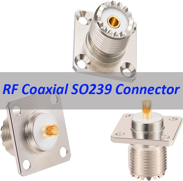
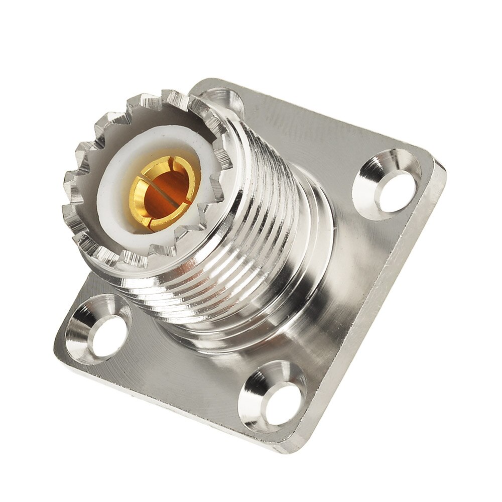
What Is an RF Coaxial SO239 Connector?
- An RF coaxial SO239 connector is a female RF connector used to interface coaxial cables in radio-frequency systems.
- It is typically mounted on a panel or chassis and serves as the fixed connection point on equipment.
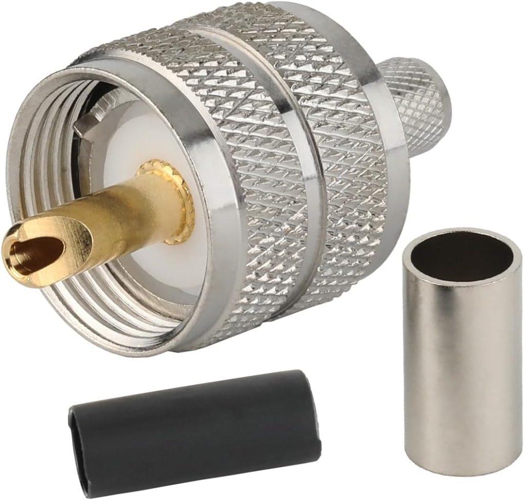
- It is designed to mate with a PL259 male plug, forming a widely used RF connector pair.
Key definition and features
- SO239 = female (jack/socket) in a UHF connector system
- Supports coaxial signal transmission with shielding to reduce interference
- Features:
- threaded coupling for secure connection
- robust metal structure for durability
- easy manual installation
- Commonly used in low to mid-frequency RF applications (typically below a few hundred MHz)
Mating connector
- The matching connector is PL259 (male plug)
- Together they form a standard UHF RF connection system
- Widely used for:
- antenna cables
- RF communication equipment
- test and measurement setups
Alternative names
SO239 connectors may also be labeled as:
- UHF female connector
- SO-239 socket
- UHF chassis connector
- RF coaxial UHF jack
Installation methods
SO239 connectors are usually fixed to equipment using:
- Panel mount
- threaded body with nut
- most common structure
- Flange mount
- secured with screws
- better mechanical stability
- Chassis mount
- integrated into device housing
- used as external RF interface
Cable termination methods
In RF cable or assembly integration, the connection typically uses:
- Solder termination
- center conductor soldered
- shield grounded to connector body
- suitable for stable, low-volume builds
- Crimp termination
- faster and more consistent
- preferred for batch production
SO239 vs other RF connectors
| Connector | Size | Frequency | Key Advantage | Typical Use |
|---|---|---|---|---|
| SO239 | Large | Low–mid | Strong, easy to use | Antennas, radio systems |
| SMA | Small | High (GHz) | High precision, compact | RF modules, PCB design |
| BNC | Medium | Mid | Quick connect | Lab, testing |
| N-type | Large | Higher than SO239 | Weatherproof, stable | Outdoor RF, base stations |
Key differences vs SMA
- SO239 is larger and more rugged
- SMA is smaller and designed for high-frequency performance
- SO239 is better for:
- antenna connections
- field installation
- SMA is better for:
- RF PCB design
- high-frequency signal integrity
Quick summary
- SO239 is a female RF coaxial connector
- Mates with PL259 male plug
- Also called UHF female connector
- Installed via panel or chassis mounting
- Supports solder or crimp cable termination
- Preferred for durable, lower-frequency RF applications
How Does an SO239 Connector Work in RF Coaxial Systems?
In RF coaxial systems, the SO239 connector serves as the physical and electrical bridge between a coaxial cable and the PCB. It maintains a consistent 50Ω characteristic impedance along the signal path, minimizing reflections and preserving signal integrity from the cable through the PCB trace.
| Function | Description |
|---|---|
| Signal Transmission | Carries RF signals with low loss and minimal interference |
| Impedance Matching | Maintains 50Ω impedance to reduce reflection |
| Mechanical Coupling | Threaded connection ensures secure mating with PL259 |
What Is the Difference Between SO239 and PL259 Connectors?
Though often mentioned together, SO239 and PL259 serve different roles in an RF connection.
| Feature | SO239 | PL259 |
|---|---|---|
| Gender | Female (socket) | Male (plug) |
| Mount Type | Panel/chassis mount (often on PCB) | Cable mount |
| Typical Use | PCB or equipment interface | Cable termination |
| Thread Size | Standard UHF thread | Standard UHF thread |
Understanding this distinction is crucial when selecting components for your RF Coaxial SO239 Connector integration in PCBA.
What Are the Key Specifications of an RF Coaxial SO239 Connector?
Key specifications determine whether an SO239 connector is suitable for a given PCBA project.
| Specification | Typical Value |
|---|---|
| Impedance | 50Ω |
| Frequency Range | DC – 300 MHz (up to 500 MHz in some designs) |
| Voltage Rating | 500V RMS |
| Insulation Resistance | ≥ 1000 MΩ |
| Contact Resistance | ≤ 1.0 mΩ (center contact) |
These parameters directly impact how an RF Coaxial SO239 Connector performs in real-world PCBA environments.
What Applications Use RF Coaxial SO239 Connectors?
SO239 connectors are widely adopted in applications requiring robust RF connectivity.
- Amateur radio (ham radio) transceivers
- Marine VHF communication systems
- CB radios and vehicle-mounted RF equipment
- Test and measurement instruments
- Industrial RF control panels
Their reliability makes them a preferred choice for PCBA designs in both commercial and industrial sectors.
What Frequency Range Does an SO239 Connector Support?
- The RF coaxial SO239 connector was historically classified as a UHF connector, suggesting a frequency range of 300–3000 MHz.
- In practical engineering use, it is not optimized for true UHF performance due to its non-constant impedance structure.
Practical frequency performance
- In most RF systems, SO239 connectors are typically used within:
- DC to 100 MHz → stable and reliable
- 100 to 300 MHz → acceptable with moderate loss
- Above 300 MHz → performance degrades noticeably
- For this reason, engineers generally treat SO239 as a low to mid-frequency connector.
Why SO239 has frequency limitations
- The connector structure does not maintain a constant 50Ω impedance
- Internal geometry is not optimized for high-frequency signal control
- This results in:
- increased signal reflection (higher VSWR)
- higher insertion loss
- reduced signal integrity at higher frequencies
Performance considerations in PCBA
- Keep RF trace length as short as possible from connector to circuit
- Ensure strong grounding and shielding
- Avoid using SO239 in:
- high-frequency RF circuits
- microwave or GHz-level designs
- Best suited for:
- antenna interface ports
- external RF cable connections
- lower-frequency communication modules
Comparison with high-frequency connectors
| Connector | Typical Frequency Range | Impedance Control | Suitable For |
|---|---|---|---|
| SO239 | DC–300 MHz | Limited | Antennas, radio systems |
| SMA | Up to 18 GHz+ | Excellent | RF PCB, high-frequency modules |
| N-type | Up to 11 GHz | Good | Outdoor RF, base stations |
Engineering recommendation
- Use SO239 when:
- frequency is below 300 MHz
- mechanical strength is required
- compatibility with PL259 cable assemblies is needed
- Choose SMA or N-type when:
- frequency exceeds 300 MHz
- signal integrity is critical
- controlled impedance is required
Quick summary
- SO239 performs best below 300 MHz
- It is not ideal for true UHF or microwave applications
- Above this range, loss and reflection increase
- For high-frequency PCBA, SMA or N-type connectors are better choices
How to Install an RF Coaxial SO239 Connector Correctly?
Proper installation ensures electrical performance and mechanical durability.
- Design PCB footprint with correct pad size and grounding vias.
- Align connector pins accurately with PCB traces.
- Solder using controlled temperature to avoid thermal damage.
- Ensure the connector body is securely fastened to the PCB or enclosure.
- Perform continuity and impedance checks post-assembly.
Correct installation directly influences how effectively the RF Coaxial SO239 Connector functions within your PCBA.
How to Choose the Right RF Coaxial SO239 Connector for Your PCBA Project?
Selecting the right connector involves balancing electrical, mechanical, and environmental factors.
| Consideration | Recommendation |
|---|---|
| Frequency Requirement | Choose connectors rated above your max operating frequency |
| Environmental Exposure | Opt for waterproof or sealed versions if needed |
| PCB Thickness | Verify mounting compatibility with board thickness |
| Plating Material | Gold-plated contacts for better corrosion resistance |
| Budget | Balance cost with required performance level |
Making informed choices here ensures optimal performance of your RF Coaxial SO239 Connector in PCBA.
In conclusion, RF Coaxial SO239 Connector plays a vital role in enabling dependable RF signal transfer in PCBA designs across communications, marine, and industrial applications. This article covered its definition, working principles, specifications, installation methods, and selection criteria to help engineers make informed decisions.
At Best Technology, we deliver precision-engineered PCBA solutions with expert RF connector integration, ensuringsignal integrity and mechanical robustness. Pls feel free to contact our team anytime at sales@bestpcbs.com for reliable, high-performance RF PCBA manufacturing.
FAQs About RF Coaxial SO239 Connector
Can SO239 be used above 300 MHz?
Yes, but performance may degrade; consider higher-grade RF connectors for >500 MHz.
Is SO239 compatible with 75Ω systems?
No, it is designed for 50Ω systems; using it in 75Ω setups causes mismatch.
Does SO239 require special tools for installation?
Basic soldering and alignment tools suffice; no specialized crimping is needed.