 language
How to Tell Passive and Active Elements in Circuits?
Are you struggling to clearly identify passive and active elements when reviewing schematics or BOM lists, especially in complex assemblies? In real-world PCB assembly and troubleshooting, misjudging passive and active elements can lead to incorrect sourcing, testing errors, or even functional failure, particularly in mixed-signal or power designs.
What are Active and Passive Elements in a Circuit?
Active and passive elements in electronics are categorized based on how they interact with energy and signal control. Active elements are components that can supply energy or amplify signals. They require an external power source to operate and can control current flow dynamically. These elements are essential in signal processing, switching, and amplification. Passive elements, by contrast, do not generate energy. They only store, dissipate, or transfer energy within the circuit. Their behavior is linear and predictable, without the need for an external power source.
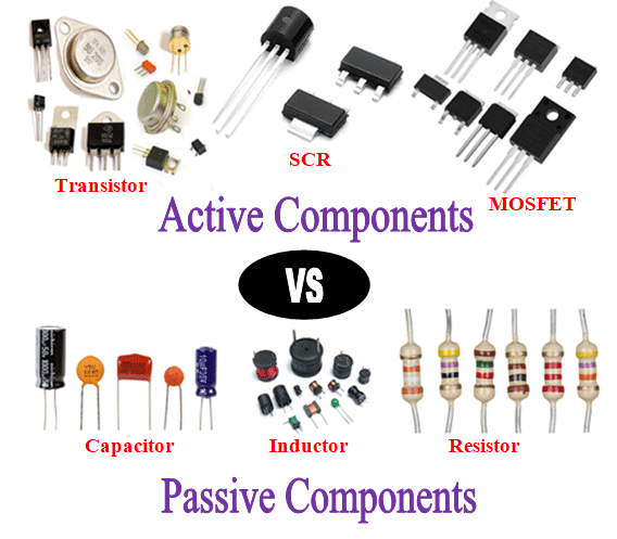
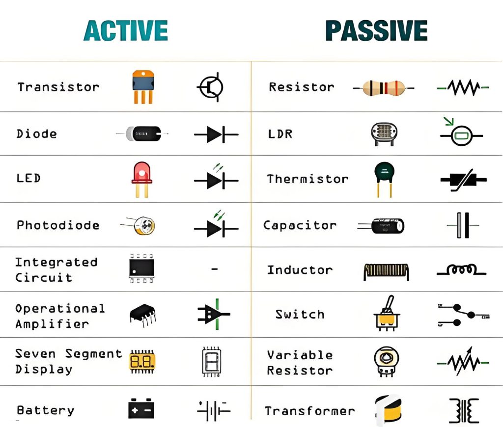
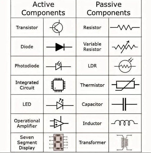
What are Examples of Active and Passive Components in Circuits?
List of Active Components Examples
- Transistors
- BJT such as NPN and PNP
- MOSFET such as NMOS and PMOS
- IGBT for high-power switching
- Application: Power conversion, switching regulators, motor drivers
- Integrated Circuits
- Microcontrollers and processors
- Analog ICs such as op-amps and comparators
- Power management ICs including DC-DC converters and LDO regulators
- RF ICs for communication modules
- Application: Signal processing, control logic, system integration
- Diodes
- Standard rectifier diodes
- Zener diodes for voltage regulation
- Schottky diodes for fast switching
- LEDs for indication or lighting
- Application: Rectification, protection, signal shaping
- Thyristors and Triacs
- SCR for controlled rectification
- Triac for AC power control
- Application: Industrial control, dimming systems, AC switching
- Optoelectronic Devices
- Optocouplers for isolation
- Photodiodes and phototransistors
- Application: Signal isolation, sensing, feedback loops
List of Passive Components Examples
- Resistors
- Fixed resistors including thick film and thin film
- Variable resistors such as potentiometers
- Current sense resistors with low ohmic values
- Application: Voltage division, current limiting, biasing
- Capacitors
- Ceramic capacitors for high-frequency decoupling
- Electrolytic capacitors for bulk energy storage
- Tantalum capacitors for stable capacitance
- Film capacitors for precision and stability
- Application: Filtering, energy storage, noise suppression
- Inductors
- Power inductors for DC-DC converters
- RF inductors for impedance matching
- Common mode chokes for EMI suppression
- Application: Energy storage, filtering, EMI control
- Transformers
- Isolation transformers
- Flyback transformers
- Application: Voltage conversion, isolation, power transfer
- Passive Filters and Networks
- RC, LC, and RLC networks
- EMI filters
- Application: Signal conditioning, frequency filtering
Mixed or Special Components
- Quartz crystals and oscillators
- Passive in structure but used with active circuits for clock generation
- Sensors such as thermistors or varistors
- Passive behavior but critical for system protection and feedback
- Ferrite beads
- Passive components used specifically for noise suppression
- Modules such as power modules or RF modules
- Internally contain active elements but appear as a single component
What are Difference Between Active and Passive Components in Basic Electronics?
| Criteria | Active Elements | Passive Elements |
| Energy Behavior | Can inject energy into the circuit or amplify signals | Only absorb, store, or release energy |
| Power Requirement | Require external power supply or bias voltage | Operate without external power source |
| Signal Function | Amplification, switching, modulation, control | Filtering, coupling, energy storage |
| Electrical Characteristics | Nonlinear behavior, gain or switching regions | Linear or predictable response |
| Complexity | High internal structure, multi-layer semiconductor design | Simple structure, often single-function |
| Typical Components | ICs, transistors, diodes, power devices | Resistors, capacitors, inductors |
| Role in Circuit | Define circuit functionality | Support circuit stability and performance |
| Failure Impact | Can cause full system failure | Usually affects part of circuit performance |
| Testing Method | Functional testing, programming, calibration | Value measurement such as resistance, capacitance |
| Sensitivity | High sensitivity to ESD, temperature, and handling | Lower sensitivity, but still affected by environment |
| Cost Contribution | Higher unit cost, lower quantity | Lower unit cost, higher quantity |
| Placement Consideration | Requires precise orientation and thermal management | Focus on placement accuracy and density |
| Repair and Rework | Difficult, may require reprogramming or replacement | Easier to replace or adjust |
What Tools Can Help Distinguish Between Passive and Active elements in Electronic Circuits?
In practical PCB assembly, troubleshooting, and incoming inspection, distinguishing passive and active components is not done by theory alone. It relies on a combination of electrical testing tools, documentation systems, and visual inspection methods. Using the right tools can significantly reduce misidentification risks and improve test efficiency.
Electrical Testing Tools for Component Identification
- Multimeter
- Measures voltage, resistance, and continuity
- Helps identify resistors, diodes, and basic circuit behavior
- Diode test mode can quickly confirm nonlinear characteristics of active elements
- LCR Meter
- Measures inductance, capacitance, and resistance with high accuracy
- Essential for identifying passive components such as capacitors and inductors
- Useful for verifying component values against BOM specifications
- Oscilloscope
- Observes signal waveforms in real time
- Detects amplification, oscillation, or switching behavior
- Helps confirm whether a component is actively controlling signals
- Curve Tracer
- Plots current-voltage characteristics
- Clearly distinguishes linear passive behavior from nonlinear active behavior
- Commonly used in failure analysis and advanced diagnostics
- Inspection and Identification Tools Used in PCB Assembly
- Automated Optical Inspection AOI
- Identifies component placement, orientation, and marking
- Helps differentiate ICs, transistors, and passive components based on package type
- Widely used in SMT production lines
- X-Ray Inspection
- Used for hidden joints such as BGA or QFN packages
- Confirms internal structure and solder integrity of active components
- Critical in high-reliability applications
- Component Marking Recognition Systems
- Reads SMD codes and laser markings
- Matches components to databases for quick classification
- Reduces manual identification errors during inspection
- Documentation and Digital Tools for Fast Classification
- Bill of Materials BOM
- The most reliable reference for distinguishing active and passive components
- Clearly categorizes components by type, value, and function
- In turnkey PCBA services, BOM classification is standard practice
- CAD and Schematic Software
- Tools such as Altium, KiCad, or OrCAD
- Provide symbol-based identification
- Active components are shown with control pins, passive components with simple symbols
- Datasheet Databases
- Manufacturer datasheets provide definitive classification
- Include electrical characteristics, application notes, and usage conditions
- Essential for resolving ambiguous components
- Advanced Tools for Engineering Validation
- Functional Test Systems FCT
- Validate whether a component performs active functions in-circuit
- Common in mass production testing
- In-Circuit Test ICT
- Measures component-level electrical parameters directly on the board
- Efficient for verifying passive values and detecting faults
- Thermal Imaging Camera
- Detects heat generation patterns
- Active components often generate localized heat during operation
- Useful for identifying powered devices in complex assemblies
How to Tell Passive and Active Elements in Circuits?
Below is a guide to distinguish passive and active components in circuits:
1. Check Energy Behavior
- Active: Can add energy to the circuit (e.g., a transistor amplifying a signal).
- Passive: Only dissipate, store, or transfer energy (e.g., a resistor converting current to heat, a capacitor storing charge).
2. Verify Power Requirements
- Active: Need a bias voltage or external power supply (e.g., a MOSFET requiring Vgs to switch).
- Passive: Work without external power (e.g., a resistor functions with just voltage/current).
3. Analyze Signal Functions
- Active: Perform amplification, switching, modulation, or control (e.g., an op-amp boosting a signal, a diode rectifying AC).
- Passive: Enable filtering, coupling, or energy storage (e.g., an inductor in a filter circuit, a capacitor decoupling noise).
4: Examine Electrical Characteristics
- Active: Exhibit nonlinear behavior (e.g., a transistor’s gain in saturation region).
- Passive: Show linear or predictable responses (e.g., Ohm’s law for resistors, capacitance formulas for capacitors).
5. Identify Typical Components
- Active: ICs, transistors, diodes, power devices (e.g., IGBTs).
- Passive: Resistors, capacitors, inductors, transformers.
6. Assess Circuit Role
- Active: Define functionality (e.g., a microcontroller running code).
- Passive: Support stability/performance (e.g., bypass capacitors stabilizing power rails).
7. Evaluate Failure Impact
- Active: Failure may cause full system collapse (e.g., a failed amplifier shutting down a radio).
- Passive: Typically affect partial performance (e.g., a degraded resistor altering a filter’s cutoff frequency).
8. Review Testing Methods
- Active: Require functional testing, programming, or calibration (e.g., testing a DAC’s output accuracy).
- Passive: Tested via value measurements (e.g., resistance with a multimeter, capacitance with an LCR meter).
9. Consider Sensitivity & Cost
- Active: High sensitivity to ESD, temperature, and handling; higher unit cost but lower quantity.
- Passive: Lower sensitivity but still environment-affected; lower unit cost with higher quantities.
10. Note Placement & Repair
- Active: Need precise orientation/thermal management (e.g., heat sinks for power transistors); difficult repair (reprogramming/replacement).
- Passive: Focus on placement accuracy/density; easy repair (swap components or adjust values).
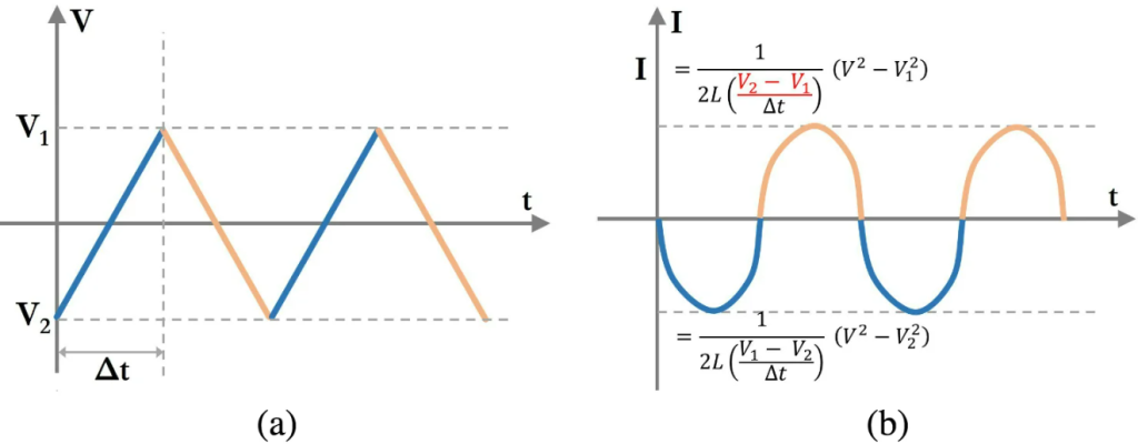
Is there a Simple Graph to Distinguish Active and Passive Elements Visually?
Yes, a simple visual method is to classify components based on their voltage and current relationship.
Passive elements typically follow linear or predictable curves. For example, resistors follow Ohm’s law, while capacitors and inductors show energy storage behavior over time.
Active elements show nonlinear characteristics. Transistors and diodes have threshold behavior, switching regions, or amplification zones. These nonlinear curves make them easy to distinguish in graphical analysis.
In practical PCB testing environments, curve tracers are often used to quickly identify whether a component behaves as active or passive.
FAQs About Active and Passive Elements in Electronics
Q1: What is an example of an active element?
A1: A common example is a MOSFET. It controls current flow and requires a gate voltage to operate, making it an active element.
Q2: Can a diode be both active and passive?
A2: Diodes are generally classified as active because they control current direction and exhibit nonlinear behavior.
Q3: Why are resistors always passive components?
A3: Resistors do not generate or amplify energy. They only dissipate energy as heat, which defines them as passive.
Q4: How important is this distinction in PCB assembly?
A4: It is critical. Active components require careful handling, programming, and testing, while passive components focus more on placement accuracy and tolerance.
Q5: Is there a quick way to identify components during inspection?
A5: Yes. Use BOM classification, component markings, and schematic references together. This is standard practice in professional PCB assembly lines.