 language
Remote Control Car PCB Circuit | Prototype to Mass Production Service
Remote control car PCB circuit is the fundamental nervous system that brings miniature vehicles to life, translating user commands into precise mechanical action. This article will explore its design intricacies, manufacturing process, and how to ensure optimal performance from prototype to high-volume production.
Turning a great concept for an RC car PCB schematic and layout into a reliable, market-ready product is fraught with challenges. Are you facing these common roadblocks?
- Persistent Signal Interference: Unreliable control, signal dropouts, or reduced range due to poor immunity against environmental RF noise.
- Complex, Error-Prone Design: Difficulty in integrating motor drivers, RF modules, and power management efficiently, leading to schematic and layout errors that cause delays.
- Prototyping Bottlenecks: Slow and expensive prototype turns that hinder iterative testing and design validation, delaying time-to-market.
- Manufacturing Inconsistency: Issues with PCB fabrication and assembly quality from suppliers, resulting in poor yield and unreliable end-products.
- Inadequate Performance Testing: Lack of thorough signal integrity, power integrity, and functional testing protocols before mass production, risking field failures.
Partnering with an expert manufacturing service is the key to navigating these hurdles. Here is how a specialized partner addresses these core issues:
- Expert Signal Integrity Design: Implementation of controlled impedance routing, proper grounding, and shielding strategies for the wireless remote control car PCB module to ensure robust communication.
- Turn-Key Design Support: Provision of design-for-manufacturing (DFM) analysis, library parts, and expert review of your remote control car circuit board design to prevent errors and optimize for performance.
- Rapid, Reliable Prototyping: Fast-turn PCB prototype services with comprehensive assembly to get functional boards in hand quickly for testing and refinement.
- High-Yield Mass Production: Scalable, high-precision manufacturing processes with strict quality control to ensure every RF remote control car receiver circuit board is built to the same high standard.
- Rigorous Pre-Production Validation: Execution of advanced electrical testing, signal integrity analysis, and functional testing on pilot runs to guarantee product reliability before full-scale rollout.
At Best Technology, we specialize in transforming your electronic concepts into high-performance, durable products. As a professional PCB and assembly manufacturer, we provide a seamless, integrated service from the initial RC car PCB schematic and layout review all the way through to efficient, cost-effective mass production. Our engineering support and stringent quality controls are designed to deliver PCBs that excel in the demanding environment of remote-controlled vehicles. For a consultation, contact us at sales@vn.danyupcbs.com.
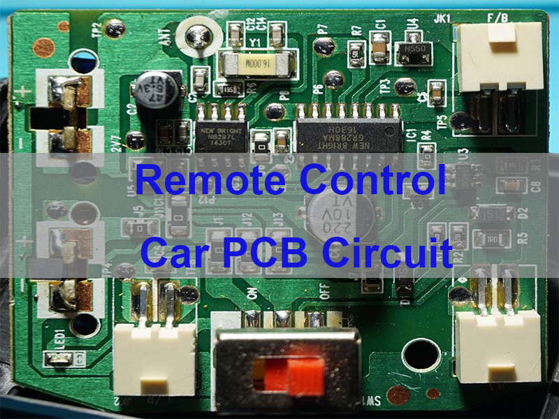
What Is a Remote Control Car PCB Circuit and How Does It Work?
A Remote Control Car PCB (Printed Circuit Board) is the dedicated platform that hosts and interconnects all electronic components required for the car’s operation. It acts as the central hub, processing commands from the transmitter and directing power to the motors and servos.
Key Components and Their Functions:
| Component | Function |
|---|---|
| RF Receiver Module | Receives and decodes signals from the remote |
| Microcontroller (MCU) | Processes signals and controls car functions |
| Motor Driver (H-Bridge) | Drives the motor for forward and reverse motion |
| Voltage Regulator | Provides stable power to the circuit |
| Connectors & Headers | Connects battery, motor, servo, and accessories |
Basic Workflow:
- The user presses a button on the wireless transmitter.
- The transmitter sends a coded RF signal.
- The RF remote control car receiver circuit board captures and decodes this signal.
- The decoded command is sent to the MCU on the main PCB.
- The MCU interprets the command and sends corresponding signals to the motor driver and steering servo.
- The motor driver adjusts power to the wheels, and the servo adjusts the steering angle, making the car move as directed.
In essence, the PCB ensures reliable communication and precise power distribution, making responsive and enjoyable control possible.
What Should Be Included in an RC Car PCB Layout?
A robust RC car PCB layout is critical for electrical performance, thermal management, and mechanical reliability. It goes beyond simply connecting components and requires careful planning of the board’s physical architecture.
- Component Placement Strategy: Group related functional blocks together (RF section, power section, digital control). Place the receiver antenna away from noise sources like motors and power traces. Position the motor driver and voltage regulator for optimal heat dissipation.
- Power Distribution Network (PDN) Design: Use wide traces or power planes for high-current paths (battery to motor driver, motors). Ensure the input capacitor for the motor driver is placed as close as possible to its pins to suppress voltage spikes.
- Grounding Scheme: Implement a solid ground plane to provide a stable reference and shield against noise. A single, continuous ground plane is often preferred over split grounds to avoid ground loop issues in mixed-signal designs.
- Signal Routing Priorities: Route sensitive RF lines (from receiver to antenna) as controlled impedance traces, keeping them short and away from other signals. Group and route motor control signals together, but separate them from sensitive analog or RF lines.
- Thermal Management: Use thermal vias under hot components (like motor driver ICs) to transfer heat to a bottom-side copper pour or external heatsink. Ensure adequate copper area for heat spreading.
- Mechanical and DFM Considerations: Place mounting holes in corners for secure attachment to the chassis. Follow your manufacturer’s Design for Manufacturing (DFM) rules for trace width, spacing, and hole sizes to ensure a reliable and cost-effective board.
A well-executed remote control car circuit board design prioritizes isolation between noisy and sensitive circuits, provides robust power delivery, and manages heat effectively, forming the foundation for a high-performance vehicle.
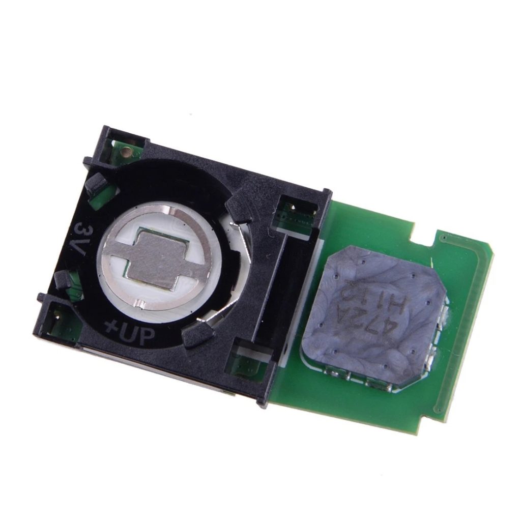
What Is the Role of RF Remote Control Car Receiver Circuit Board?
The RF remote control car receiver circuit board is a critical subsystem dedicated solely to wireless communication. Its role is to reliably capture the transmitted signal in a noisy environment, demodulate it, and deliver clean digital commands to the main controller.
- Signal Reception: The onboard antenna captures the specific RF signal (e.g., 2.4GHz or other licensed frequencies) sent by the transmitter.
- Amplification and Filtering: The weak incoming signal is amplified. Band-pass filters reject out-of-band interference from Wi-Fi, Bluetooth, or other RF sources.
- Demodulation: The RF carrier wave is stripped away to recover the original digital command data (e.g., a pulse-position modulation signal for servo control).
- Decoding & Output: The recovered data is decoded by an integrated circuit. The receiver then outputs standard control signals, most commonly PWM (Pulse Width Modulation) signals, to the main MCU for each channel (throttle, steering, etc.).
Key Characteristics of a Quality Receiver Board:
- High Sensitivity: Ability to work with very weak signals, extending operational range.
- Selectivity & Anti-Interference: Excellent filtering to ignore signals on adjacent frequencies, crucial for operating multiple cars simultaneously.
- Low Latency: Fast signal processing to ensure near-instantaneous response to user input.
- Compact Form Factor: Designed to fit within the constrained space of an RC car chassis.
In summary, this specialized board is the gateway for all user commands. Its performance directly dictates the control range, responsiveness, and reliability of the entire remote control car PCB circuit.
How To Improve Signal Integrity in a Remote Control Car PCB Circuit?
Signal Integrity (SI) ensures that digital signals arrive at their destination without significant distortion, which is paramount for reliable control. Poor SI can cause glitches, resets, or erratic behavior.
Primary Strategies for SI Enhancement:
| Strategy | Application in RC Car PCB | Benefit |
|---|---|---|
| Controlled Impedance Routing | Used for RF and fast signal traces | Improves signal stability |
| Proper Grounding | Use a solid ground plane | Reduces noise and interference |
| Decoupling Capacitor Placement | Place capacitors close to IC power pins | Stabilizes power supply |
| Trace Separation | Keep motor traces away from RF traces | Lowers crosstalk |
| Minimizing Loop Areas | Keep signal and return paths close | Reduces EMI |
Practical Implementation Checklist:
- Segment the Board: Physically separate the “quiet” zone (MCU, receiver) from the “noisy” zone (motor driver, battery inputs).
- Power Integrity First: A clean power supply is the foundation of good SI. Use a multi-stage filter: bulk capacitor (e.g., 100µF) near battery input, medium capacitor (e.g., 10µF) near ICs, and local decoupling caps (0.1µF) at eachpower pin.
- Route Critically Sensitive Lines First: Prioritize the antenna feedline. Keep it short, straight, and with a continuous ground plane beneath it.
- Review and Simulate: Use your PCB tool’s design rule checks (DRC) and, if possible, basic SI simulation tools to identify potential issues like excessive stub lengths or impedance discontinuities.
By proactively managing these factors during the RC car PCB schematic and layout phase, you build inherent robustness against noise, leading to a more reliable and responsive vehicle.
How To Manufacture and Assemble a Remote Control Car PCB Circuit Efficiently?
Efficient manufacturing bridges the gap between a validated prototype and a successful commercial product. It requires a streamlined process focused on quality, consistency, and scalability.
The Efficient Production Pathway:
- Design Finalization & DFM Review: Submit complete Gerber, drill, and BOM files. A good manufacturer will conduct a Design for Manufacturability (DFM) analysis, flagging issues like insufficient copper-to-edge clearance or component spacing conflicts that could cause yield loss.
- Material Procurement & PCB Fabrication: The manufacturer sources the specified PCB laminate (e.g., FR-4) and begins fabrication (imaging, etching, lamination, drilling, plating). For high-volume orders, panelization—arranging multiple PCBs on a single panel—optimizes material use and machine time.
- Solder Paste Application & Component Placement: Solder paste is precisely applied to pads using a stencil. Then, high-speed pick-and-place machines accurately populate components onto the board. This is where the quality of the bare RF remote control car receiver circuit board meets precision assembly.
- Reflow Soldering: The assembled panel passes through a reflow oven with a controlled temperature profile, melting the solder paste to form permanent electrical and mechanical connections.
- Inspection, Testing, and Programming: This critical phase includes:
- Automated Optical Inspection (AOI): Checks for solder bridges, missing, or misaligned components.
- In-Circuit Test (ICT) or Flying Probe Test: Verifies electrical connectivity and checks for shorts/opens.
- Functional Test: The assembled board is powered on and put through its paces—checking RF link, motor outputs, and controls.
- MCU Programming: Flashing the firmware onto the microcontroller.
Efficiency is achieved by selecting a manufacturer with an integrated, automated workflow, clear communication, and a focus on getting the process right the first time to minimize rework and delays.
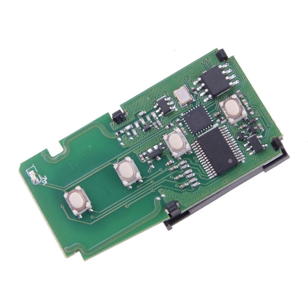
Case of Bare RF Remote Control Car Receiver Circuit Board and the Assembly By Best Technology
A client approached us with a bare RF remote control car receiver circuit board design that was experiencing intermittent range issues during their prototype phase. Their challenge was to identify the root cause and transition to a robust, high-yield mass production solution.
Our Integrated Approach:
- Deep-Dive Design Analysis: Our engineers reviewed the client’s layout, identifying a suboptimal antenna matching network and a discontinuous ground plane beneath the RF trace, which degraded signal strength.
- Rapid Design Revision & Prototyping: We proposed and implemented minor layout modifications. Within one week, we delivered a new batch of fabricated bare boards and fully assembled them with the required RF components and MCU.
- Comprehensive Validation Testing: We subjected the new assemblies to rigorous testing beyond the client’s initial scope:
- Network Analyzer Verification: Confirmed the antenna’s impedance matching for optimal performance.
- Range & Bit Error Rate (BER) Testing: Quantified the improvement in reliable control distance.
- Environmental Stress Testing: Checked performance under varying voltage levels to simulate a draining battery.
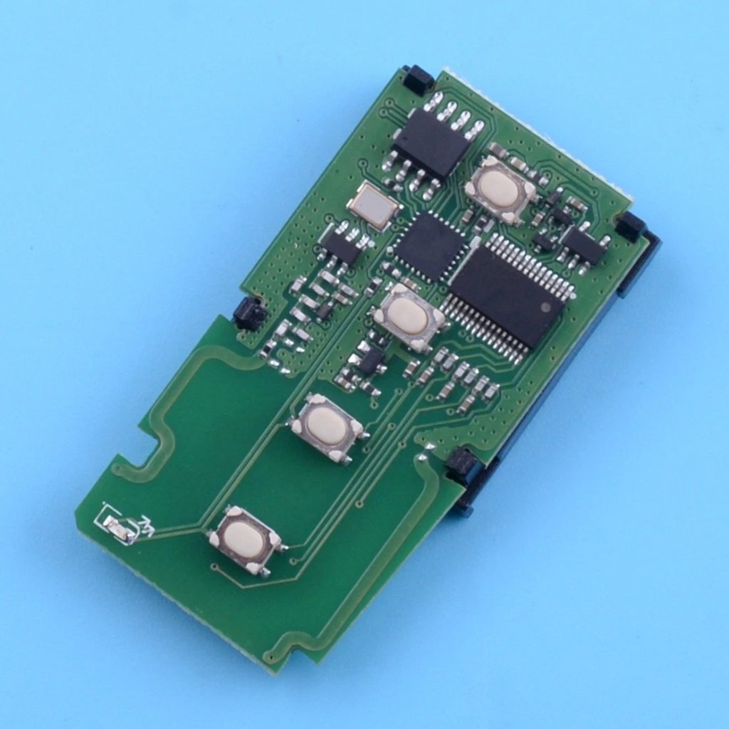
- Smooth Ramp-Up to Mass Production: With the design validated, we moved the optimized design into our high-volume production line. Our automated assembly and strict quality control ensured every unit performed identically to the approved prototype.
The outcome was a reliable receiver module with a 40% improvement in stable operating range, zero production-related field failures in the first 10,000 units, and a streamlined supply chain for the client.
Why Choose Best Technology for RF Remote Control Car Receiver Circuit Board Manufacturing?
Selecting the right manufacturing partner is crucial for the success of your product. Best Technology offers distinct advantages tailored to the needs of consumer electronics and RC applications.
- Expertise in Mixed-Signal & RF Design: We understand the critical interplay between digital control, power circuits, and sensitive wireless remote control car PCB module design. We proactively address SI and EMI challenges.
- True End-to-End Service: We are a one-stop shop, managing the entire journey from remote control car circuit board design review, PCB fabrication, component sourcing, and precise assembly, to final testing and shipment.
- Rapid Prototyping to High-Volume Scale: We facilitate fast, iterative prototyping to perfect your design, then seamlessly scale production using the same controlled processes and quality standards, ensuring consistency from the first unit to the ten-thousandth.
- Rigorous Quality and Testing Regime: Our commitment goes beyond basic assembly. We invest in advanced testing equipment (AOI, Flying Probe, Functional Testers) to catch defects early, ensuring the RF remote control car receiver circuit board you receive is fully functional and reliable.
- Proactive Engineering Support: We act as an extension of your team. Our engineers provide actionable DFM/DFA feedback and technical insights during the design phase to prevent costly mistakes and optimize for performance and manufacturability.
All in all, a remote control car PCB circuit is the engineered core that determines the responsiveness, reliability, and fun of the final product. This article has covered its functional principles, critical design and signal integrity considerations, and the pathway to efficient manufacturing.
Navigating from a prototype to mass production requires a partner with the right technical expertise and manufacturing rigor. Best Technology specializes in providing that complete solution. We combine engineering insight with advanced manufacturing capabilities to deliver robust, high-performance PCBs for your RC applications. Pls feel free to contact our team anytime at sales@vn.danyupcbs.com to get started.
FAQs About Remote Control Car PCB Circuit
Q1: What is the typical range for a 2.4GHz RC car PCB?
A: With a well-designed RF remote control car receiver circuit board and good antenna layout, typical range is 100-200 meters in open space. Range is affected by output power, receiver sensitivity, antenna design, and environmental obstacles.
Q2: Can you assemble both the main control board and the receiver module?
A: Absolutely. Best Technology provides full Turn-Key assembly services. We can manufacture and assemble the main remote control car PCB circuit, the separate receiver module, and any other peripheral boards, ensuring complete compatibility and quality.
Q3: What file formats do you need to start a project?
A: We require the standard manufacturing file package: Gerber files (RS-274X) for each PCB layer, NC Drill files, a complete Bill of Materials (BOM) with manufacturer part numbers, and a pick-and-place file for component locations. A schematic is also highly beneficial for our engineering review.
Q4: How do you ensure quality during mass production?
A: Quality is embedded in our process through Automated Optical Inspection (AOI) after solder paste printing and after reflow, electrical testing (Flying Probe/ICT), and mandatory functional testing on a sample from every production batch. We provide detailed quality reports for traceability.