 language
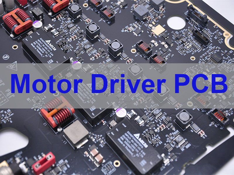
Complete Motor Driver PCB Fabrication To Full Turnkey Assembly
Motor driver PCB is the critical power stage that converts control signals into the high current needed to drive motors in everything from drones to industrial robots. This guide provides a clear roadmap for designing and manufacturing reliable motor driver boards, from initial pcb layout to full turnkey assembly.
Many engineers face significant hurdles when developing motor drivers, such as managing heat in compact designs, ensuring signal integrity amid electrical noise, and finding a manufacturer that can reliably scale from prototype to production.
Common Challenges with Motor Driver PCBs:
- Heat buildup from high-current switching components
- Signal noise and EMI interfering with control circuits
- Power integrity issues causing voltage spikes
- Long lead times delaying prototype testing
- Finding suppliers that handle both fabrication and assembly
How Best Technology Solves These Problems:
- Specializes in heavy copper PCBs (up to 20oz) and Metal Core PCBs for superior thermal management
- Provides expert PCB layout guidelines to minimize noise and optimize performance
- Offers complete turnkey assembly with component sourcing
- Delivers quick-turn prototypes in as little as 24 hours
- Maintains IATF 16949 certification for automotive-grade quality
With nearly 20 years of PCB manufacturing experience, Best Technology serves clients globally with a 260,000 sq.ft facility and full technical support. Pls feel free to contact us at sales@vn.danyupcbs.com to discuss your motor driver PCB project.
What Is Motor Driver PCB?
A Motor Driver PCB is the dedicated circuit board that amplifies low-power control signals to deliver the high current required by electric motors. It serves as the critical interface between intelligent controllers and physical motion.
Core Components:
- Power MOSFETs/IGBTs for switching high currents
- Gate driver ICs to control the power switches
- Current sensing circuitry for feedback and protection
- Voltage regulators and filtering components
- Thermal management features (copper pours, thermal vias)
Which PCB Technology is Best for Your BLDC PCB Motor Driver?
Choosing the right PCB technology directly impacts the performance, reliability, and cost of your BLDC motor driver.
PCB Technology Comparison:
| Technology | Best For | Key Advantage |
|---|---|---|
| Standard FR-4 | Low to medium power applications | Cost-effective, readily available |
| Heavy Copper FR-4 | High-current drivers (3oz+) | Excellent current capacity, good thermal performance |
| Metal Core PCB | Applications needing superior heat dissipation | Direct heat sinking through aluminum/copper substrate |
| Ceramic PCB | Extreme thermal/performance demands | Exceptional thermal conductivity (>150 W/mK) |
For most BLDC motor driver applications, Heavy Copper FR-4 provides the optimal balance of performance, design flexibility, and cost-effectiveness.
What Are the Differences Between Motor Driver PCBA And Motor Control PCBA?
Understanding this distinction is crucial for specifying the right solution for your project.
- Motor Driver PCBA = Power stage only. Contains power switches, drivers, and protection circuits.
- Motor Control PCBA = Complete system. Includes the driver section PLUS microcontroller, power supply, communications, and sensor interfaces.
A motor driver is a component within a motor control system. We provide complete solutions for both standalone driver boards and fully integrated control systems.
How To Combine Arduino with Motor Driver in One PCB?
Integrating an Arduino-compatible microcontroller with a motor driver creates a compact, embedded motion controller. Follow these key principles:
- Partition Your Design: Keep high-power motor circuits physically separate from sensitive control electronics
- Implement Robust Power Design: Use separate power planes/regulators for motor and logic sections
- Follow Layout Best Practices:
- Minimize high-current loop areas
- Use star-point grounding
- Add thermal vias under power components
- Include Programming Interface: Incorporate USB-to-serial circuitry for easy firmware updates
Our engineering team can review your integrated design and provide DFM feedback before manufacturing begins.
How to Lay Out Your Motor Driver PCB Design for Optimal Performance and Reliability?
Proper layout is non-negotiable for motor driver success. Follow these essential guidelines:
Five Critical Layout Rules:
- Minimize power loop inductance – Place MOSFETs and capacitors close together
- Use solid ground planes – Provide low-impedance return paths
- Implement thermal vias – Conduct heat away from power components
- Keep gate drive traces short – Route directly from driver IC to MOSFET gates
- Protect sensitive signals – Route current sense lines as differential pairs away from noise sources
These practices ensure stable switching, efficient heat dissipation, and reliable operation in demanding environments.
What Certifications Should a Reliable China BLDC Motor Driver PCB Factory Have?
Certifications validate a factory’s commitment to quality and reliability—essential for motor drivers that may go into safety-critical applications.
Essential Certifications:
- IATF 16949 – Automotive quality management (highest standard)
- AS9100D – Aerospace quality management system
- ISO 13485 – Medical device quality management system
- ISO 9001 – Quality management system foundation
- UL Recognition – Safety compliance for PCBs
- RoHS/REACH – Environmental compliance
Best Technology maintains IATF 16949, ISO 9001, AS9100D, ISO 13485 and RoHS/REACH certifications, ensuring your BLDC motor driver PCBs meet the most rigorous international standards.
How Do Best Technology Ensure Motor Driver PCB Quality?
Quality is engineered into every production stage through a systematic approach:
Four-Stage Quality Process:
- Material Control – Verified substrates and copper from approved vendors
- Process Monitoring – Real-time impedance and dimensional checks
- 100% Electrical Testing – Flying probe testing of every board
- Final Verification – IPC standards compliance and full documentation
This certified system ensures every motor driver PCB performs reliably in your application.
Technical Capability for Motor Driver PCB Manufacturing
Best Technology provides comprehensive solutions for motor driver development:
Fabrication Capabilities:
- Layers: 1-32 layers
- Copper Weight: Up to 20oz
- Materials: FR-4, High-Tg, Rogers, Aluminum, Ceramic
- Min Trace/Space: 3/3 mil
Assembly Services:
- Turnkey Assembly with component sourcing
- Precision Placement: 01005 components, 0.2mm BGA
- Full Testing: AOI, X-Ray, SPI, functional testing
Specialty Boards:
- Metal Core PCBs (1-10 layers)
- Ceramic PCBs (Al₂O₃, AlN)
- Flex/Rigid-Flex for dynamic applications
Case of Quick Turn Motor Driver PCB by Best Technology
Project: High-Current BLDC Motor Driver Prototype
Challenges:
- 4-layer design with 3oz copper
- Aggressive thermal requirements
- 7-day total turnaround needed
Our Solution:
- Activated expedited prototyping line
- Parallel processing of fabrication and component sourcing
- Overnight electrical testing
Result: Delivered 5000 fully assembled, tested boards in 7 days, enabling successful system validation ahead of schedule.
In a nutshell, a well-designed and manufactured motor driver PCB is fundamental to creating efficient, reliable motion control systems. Success requires expertise in power electronics, thermal management, and high-reliability manufacturing.
Best Technology delivers complete motor driver PCB fabrication to full turnkey assembly with the technical depth and quality systems needed for demanding applications. From quick-turn prototypes to volume production, we provide the engineering partnership to bring your motor control projects to market successfully. Ready to develop your next motor driver? A warm welcome to contact us at sales@vn.danyupcbs.com for a free DFM analysis and project quote.
FAQs About Motor Driver PCB
Q: What files do I need for a motor driver PCB quote?
A: Provide Gerber files, BOM, and desired quantity. We’ll return a complete turnkey quote within 12 hours.
Q: Can you help optimize my design for thermal performance?
A: Yes. Our engineers provide DFM reviews and can recommend optimal PCB technology (Heavy Copper, MCPCB, etc.) based on your thermal requirements.
Q: What is your quick-turn capability?
A: We deliver 2-layer prototypes in 24 hours, and 4-layer boards in 2-3 days. Turnkey assembly adds 3-5 days depending on component availability.
Q: Do you offer conformal coating?
A: Yes. We provide acrylic, silicone, or urethane conformal coating for protection in harsh environments.
Q: What materials are best for high-voltage motor drivers?
A: Materials with high CTI rating (>400), appropriate dielectric thickness, and ENIG surface finish typically perform best for high-voltage applications.