 language
End-To-End Motor Control PCBA For Electric Motor
Motor control PCBA is the assembled brain of any modern motor, integrating the necessary circuitry and components to precisely command motion, speed, and torque. This guide will explore the essentials of designing, specifying, and manufacturing reliable PCBA for electric motor applications, from hydraulic pumps to traction drives.
Ever wonder if your motor controller’s performance or reliability issues stem from its Printed Circuit Board Assembly? The fundamental fault of many motor drive failures can often be traced back to the PCBA, influenced by both external factors like harsh operating environments and internal causes like poor thermal design or inadequate current handling. Identifying the right manufacturing partner is crucial to overcoming these challenges.
Key Customer Pain Points in Motor Control PCBA:
- Managing extreme heat and high current densities in compact power stages.
- Ensuring long-term reliability against constant vibration, thermal cycling, and contaminants.
- Navigating complex component sourcing and supply chain delays for a custom PCB assembly for motor manufacturers.
- Balancing high performance with cost-effectiveness, especially for low volume PCB for motor prototype and production runs.
- Achieving timely, transparent delivery of a complete, tested assembly.
Best Technology provides targeted solutions:
- Advanced Thermal & Power Management: Expertise in heavy copper PCB for motor drives (up to 20oz) and Metal Core PCBs (MCPCBs) for superior heat dissipation.
- Robust, Application-Tailored Manufacturing: We build high reliability PCB assembly for motor applications, adhering to strict standards and offering conformal coating for harsh environments.
- Full Turnkey Supply Chain Management: As an end-to-end PCBA for electric motor company, we handle all component sourcing from authorized distributors, mitigating supply risk.
- Cost-Optimized Engineering Support: Our engineers provide bespoke DFM advice to optimize your design for manufacturability and cost without sacrificing quality for any volume.
- Streamlined Process & Communication: We offer clear timelines, online WIP tracking, and dedicated project management to ensure on-time delivery.
Best Technology was originally founded in 2006 and has 20 years background in the motor PCB layout and manufacture of advanced circuit boards. We are a professional PCB/PCBA factory offering a true one-stop solution, from design and PCB fabrication and assembly to full box-build. With a monthly capacity of 260,000 ft² and certifications including IATF 16949, we serve clients across Europe, America, Australia, Israel and Worldwide. For your motor controller PCBA needs, pls feel free to contact us at sales@vn.danyupcbs.com.
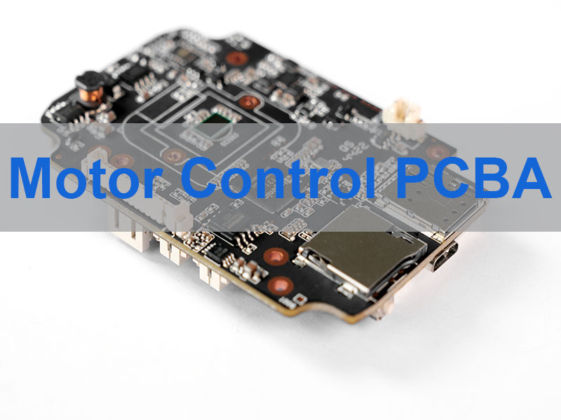
What Is Motor Control PCBA?
A Motor Control PCBA (Printed Circuit Board Assembly) is the fully populated and soldered circuit board that forms the operational heart of an electronic motor controller or drive. It integrates a microcontroller or DSP, gate drivers, power semiconductors (like MOSFETs or IGBTs), sensors, and support circuitry to execute control algorithms, translate low-power commands into high-power outputs, and provide protection and feedback. Unlike a bare PCB, the PCBA is a functional, ready-to-integrate sub-system critical for applications from treadmill motor controller PCBs to explosion proof motor control PCBs.
Core Components of a Typical Motor Control PCBA:
- Control Unit: MCU, FPGA, or DSP to run control algorithms (e.g., FOC for BLDC motor controller PCBs).
- Power Stage: IGBTs/MOSFETs and drivers for switching high currents.
- Power Supply: Converts input voltage to stable levels for different board sections.
- Feedback Network: Current shunts, Hall sensors, or encoders for closed-loop control.
- Communication Interfaces: CAN, Ethernet, or RS-485 for system integration.
- Protection Circuitry: Over-current, over-temperature, and short-circuit safeguards.
In summary, the motor control PCBA is where the intelligence and muscle of motor control converge, determining the efficiency, responsiveness, and reliability of the entire drive system.
What Are the Applications of Motor Control PCB Assembly?
Motor control PCB assembly enables precise motion control in a wide variety of demanding industries. The technology behind a DC motor speed control PCB is versatile, adapting to vastly different power levels and environmental challenges.
Key Application Areas:
- Industrial Automation & Machinery: Drives for conveyor belts, robotic arms, and materials handling equipment. This includes PCBs for hydraulic pump motor control and valve actuation.
- Automotive & Mobility: Traction motor control board assembly for electric vehicles, forklifts, and scooter motor controller PCBs. Also covers cooling fans and pumps.
- Consumer & Commercial Appliances: Drives in washing machines, HVAC blowers, and treadmill motor controller PCBs.
- Aerospace & Defense: Actuators for flight controls and aircraft ground support equipment.
- Energy & Harsh Environments: Controllers for wellhead control panels and ATEX & IECEx certified systems, requiring PCBs for explosion-proof motor ATEX certified designs.
Application-Specific PCB Requirements Table:
| Application | Key PCB Requirements | Typical PCB Type |
|---|---|---|
| High-Power Traction Drives | Heavy copper (3oz+), high thermal reliability. | Multi-layer PCB (often >6 layers). |
| Compact Servo Drives | High density, impedance control. | HDI or standard multi-layer PCB. |
| Explosion-Proof Enclosures | Maximal reliability, minimal heat, specialized coating. | High reliability PCBA. |
| Cooling Fan Drives | Cost-effective, good thermal performance. | Aluminum PCB (MCPCB) or FR4. |
Ultimately, the application dictates the PCB technology, pushing the need for bespoke solutions to meet individual customer requirements for performance, size, and durability.
How To Choose the Right PCB for High-Performance Motor Control?
Selecting the optimal PCB technology is critical to unlocking your motor’s performance, reliability, and efficiency. The choice impacts heat management, current capacity, and signal integrity. Here’s a breakdown of key technologies we provide:
Key PCB Technologies for Motor Control:
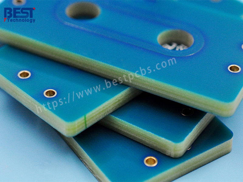
- Heavy Copper PCBs (e.g., 3oz to 20oz): Essential for high-power motor drives to carry large currents with low loss and improved thermal performance. Ideal for the power stage of traction motor controller PCBs.
- Metal Core PCBs (MCPCB): Incorporate an aluminum or copper base layer for exceptional heat sinking. Perfect for LED drives, power converters, and areas with concentrated heat sources.
- High-Frequency/RF PCBs: Use specialized laminates (Rogers, Taconic) for stable dielectric constant and low loss at high frequencies, crucial for high-speed switching and minimal noise.
- High-Density Interconnect (HDI) PCBs: Feature micro-vias and finer lines, allowing for miniaturization of complex controllers, such as compact servo drives.
- Multi-layer PCBs (4-32 Layers): The backbone of complex industrial motor controllers, providing dedicated power/ground planes and ample routing space for noise separation.
- Rigid-Flex PCBs: Offer mechanical flexibility and reliability in applications with moving parts or space constraints, reducing connection points.
Choosing correctly involves analyzing current levels, switching frequencies, thermal load, and space constraints. Partnering with an experienced manufacturer like Best Technology ensures you get a bespoke recommendation that balances all factors for optimal motor control PCB board performance. Please let us know if you require any additional information on how we can support your motor control PCB projects.
Which PCB Surface Finish is Right for Your Motor Control Board?
The surface finish is your PCB’s first line of defense, protecting the copper traces from oxidation and ensuring a reliable, solderable surface. In the demanding environments of motors—subject to vibration, thermal cycles, and potential contaminants—the wrong choice can lead to field failures.
Comparing Common Surface Finishes for Motor Control PCBAs:
| Finish | Pros | Cons | Best For |
|---|---|---|---|
| ENIG (Immersion Gold) | Flat, good solderability, long shelf life. | Higher cost, risk of “black pad”. | Most motor control PCBAs, fine-pitch, multiple reflow. |
| HASL | Low cost, robust solderability. | Uneven surface, thermal shock. | Cost-sensitive, larger-pitch boards. |
| OSP | Flat, low cost. | Short shelf life, delicate. | Quick-turn prototypes, controlled high-volume. |
| Immersion Silver | Flat, good solderability, RF-friendly. | Tarnishes, handling sensitive. | Performance-critical, managed shelf life. |
| Electrolytic Hard Gold | Extremely durable, wear-resistant. | Very high cost, special soldering. | Heavy-duty connectors (gold fingers). |
For most high reliability PCB assembly for motor applications, especially those with mixed components and a need for robustness, ENIG is the preferred choice. It provides the right balance of reliability, solderability, and surface flatness. When you request a quotation for complete PCB manufacturing and assembly based on your Gerber files, our engineering team can advise of the best surface finish if applicable to your specific design and operating environment.
What Are the Key Steps in a Motor Control PCB Layout?
A superior schematic with a poor layout is a guaranteed path to underperformance. The placement of a single high-current trace or the routing of a sensor feedback loop can mean the difference between robust operation and erratic behavior. Following a disciplined layout process is essential.
Critical Steps in Motor Control PCB Layout:
- System Partitioning & Pre-Placement: Strategically divide the board into functional blocks: high-power stage, control logic, sensitive analog sensing, and communication interfaces. Pre-place connectors, heatsinks, and large components.
- Power Stage Layout (Highest Priority):
- Minimize Power Loop Area: Keep the high-current path from the DC bus capacitors through the switches and to the motor phase output as short and wide as possible. This reduces parasitic inductance (L ~ µ₀ * Area / Length), which causes voltage spikes (V = L * di/dt).
- Use Heavy Copper and Planes: Employ heavy copper PCB for motor drives techniques and dedicated inner layers for power planes to handle current and aid heat spreading.
- Grounding Strategy: Implement a star ground or split plane strategy to prevent noisy power currents from corrupting sensitive analog ground references. Use vias generously to connect ground planes.
- Control & Signal Routing: Route critical feedback traces (e.g., from current shunts) as differential pairs directly to the controller, away from noisy areas. Maintain impedance control for high-speed signals.
- Thermal Management Planning: Identify key heat sources (MOSFETs, drivers). Incorporate thermal vias under packages to conduct heat to inner planes or a bottom-side heatsink. Plan for adequate copper pours.
- DFM/DFA Review: Before finalizing, run Design for Manufacturability and Assembly checks for proper clearances, solder mask slivers, and component spacing to ensure a smooth transition to PCB fabrication and assembly.
By meticulously following these steps, you create a motor control PCB that is electrically robust, thermally stable, and manufacturable, forming a solid foundation for a reliable end-to-end motor control PCBA.
Case Of Heavy Copper PCB Manufacturing for Motor Drives by Best Technology
Project: High-Power Motor Drive Control PCB
Challenges:
- 4-layer PCB with 3oz (105µm) heavy copper on outer layers.
- Demanding thermal and current-carrying requirements for a compact BLDC motor controller.
- Need for high reliability in an industrial environment, specified with ENIG surface finish.
- Aggressive timeline for prototype validation and pilot production.
Our Solution:
- Expert Heavy-Copper Fabrication: Leveraged 20 years of specialized process expertise to ensure perfect etching and lamination of the 3oz copper layers, preventing warpage and ensuring current integrity.
- Dedicated Engineering Support: A assigned engineer analyzed the power layout and provided proactive DFM/DFA/DFT suggestions to optimize thermal performance and manufacturability.
- Streamlined Turnkey Process: Parallel processing of PCB fabrication and assembly, including component sourcing from authorized distributors, to compress the lead time.
Result:
Delivered 500 high-reliability, fully assembled motor control PCBA units that met all electrical and thermal specifications.
A warm welcome to contact Best Technology anytime at sales@vn.danyupcbs.com for a free DFM analysis and quote. Our 260,000 sq.ft facility, ISO 9001, ISO 13485, IATF 16949, and AS9100D certifications, and 160+ technical staff are ready to support your motor control PCB project from prototype to mass production.
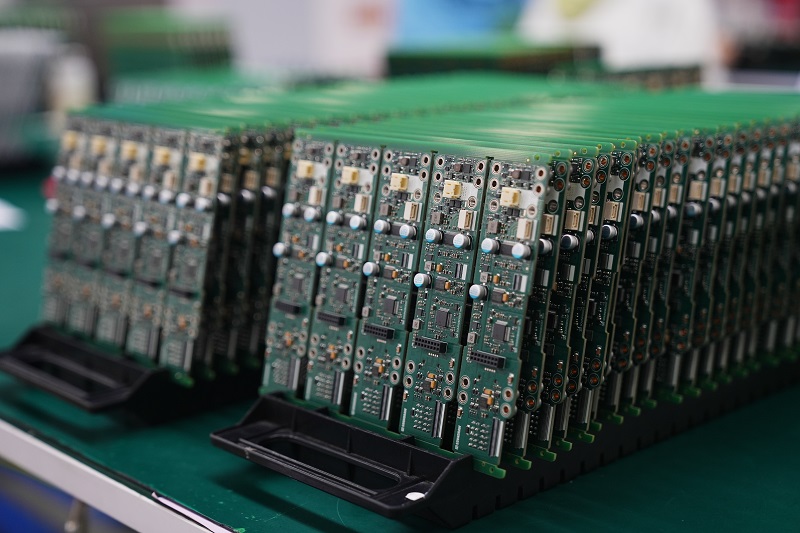
Technical Capability for Custom PCB Assembly for Motor Manufacturers
At Best Technology, our technical capabilities are built to support the stringent demands of motor manufacturers, from prototype to production. We produce a range of PCB technologies specifically suited for demanding motion control applications.
Our Core Technical Capabilities:
- PCB Fabrication
- Specific Offerings:
- Layers: 1-32 layers.
- Heavy Copper: Up to 20 oz.
- Materials: FR4, High-Tg, Rogers, Aluminum/Ceramic.
- Min Trace/Space: 3/3 mil.
- Relevance to Motor Control: Supports everything from simple DC motor controller PCBs to complex multi-layer industrial motor controllers and heavy copper power boards.
- Specific Offerings:
- PCB Assembly (PCBA)
- Specific Offerings:
- Turnkey Assembly: Full component sourcing.
- Precision: 01005, 0.2mm BGA.
- Processes: SMT, THT, Mixed assembly.
- Inspection: AOI, X-Ray, SPI, FCT.
- Relevance to Motor Control: Enables end-to-end PCBA for electric motor company needs, ensuring reliable population of dense control boards and power stages.
- Specific Offerings:
- Specialty Boards
- Specific Offerings:
- MCPCB: 1-10 layers.
- Ceramic PCB: Al₂O₃, AlN substrates.
- Flex/Rigid-Flex: For dynamic applications.
- Relevance to Motor Control: Provides solutions for extreme thermal management (MCPCB), high-voltage insulation (Ceramic), and space-constrained designs (Flex).
- Specific Offerings:
Quality & Assurance:
Our processes are certified to ISO 9001:2015 and IATF 16949:2016, with stringent in-process controls. Every motor control PCBA undergoes electrical testing and inspection, ensuring the high reliability required for hydraulic pumping or traction motors. Thanks to the engineering experience of the team, we provide actionable DFM feedback to optimize your design for cost, reliability, and performance before manufacturing begins.
Why Choose Best Technology for DC Motor Speed Control PCB And Assembly?
Selecting a partner for your DC motor speed control PCB and assembly is a critical decision that impacts your product’s performance, timeline, and bottom line. Best Technology is purpose-built to be that partner for engineers and manufacturers worldwide.
Our Decisive Advantages:
- Deep Application Expertise: With nearly 20 years in the industry, we understand the unique challenges of motor drives—from brushless DC motor controller PCB noise immunity to traction motor thermal cycling—and engineer solutions accordingly.
- True End-to-End Service: We are a one-stop shop. From managing your total combined cost for PCB fabrication and assembly to handling the entire supply chain and providing lead time certainty, we simplify your workflow.
- Bespoke Manufacturing Focus: We don’t just make standard boards. We specialize in meeting individual customer requirements, whether that’s a 3 oz copper thick board, a custom PCB assembly for motor manufacturers, or an ATEX-relevant build.
- Proven Quality & Reliability: Our certified quality management system and advanced inspection equipment ensure every motor control PCBA we ship meets the highest standards, giving you assurance in the field.
- Global Support, Local Responsiveness: Serving clients across Europe, America, Australia, Israel and Worldwide, we combine global reach with attentive, personalized project management. Our sales managers each have over 10 years of industry experience, ensuring clear communication and efficient support from inquiry to delivery.
We bridge the gap between your design and a durable, high-performance product.
In conclusion, motor control PCBA is the critical interface between command and motion, determining the efficiency, intelligence, and durability of any electric drive system. This guide has explored its applications, key technologies like heavy copper PCBs, and the meticulous process from layout to assembly.
For engineers and manufacturers facing the challenges of heat, reliability, and supply chain complexity, choosing the right production partner is paramount. Best Technology offers a compelling solution: nearly two decades of bespoke manufacturing expertise, a true end-to-end turnkey service, and a steadfast commitment to quality certified to automotive standards. We transform your specifications—from a 4-layer board with 3 oz copper to a complete ATEX-certified controller—into reliable, high-performance hardware. Pls feel free to contact our team at any time for a consultation or a detailed quote. Email us at sales@vn.danyupcbs.com.
FAQs About Motor Control PCBA
Q1: What information do you need to provide a quote for a motor control PCBA?
A: To provide an accurate and fast quotation for complete PCB manufacturing and assembly, we typically need the Gerber files (for the PCB), a complete BOM list with part numbers, and any assembly drawings. Specifying your expected volume (e.g., 500 pcs, 1000 pcs) and target lead time helps us tailor the offer.
Q2: Do you handle component sourcing for motor control PCBA projects?
A: Yes, we offer full turnkey services. We source components from authorized distributors globally. This is included in our offer for the total combined cost for PCB fabrication and assembly, simplifying procurement and ensuring component authenticity.
Q3: What is a typical lead time for a custom motor control PCBA?
A: Lead time varies based on complexity and volume. A standard 4-layer motor control PCB fabrication can take 7-10 days, with assembly adding 5-7 days. We offer expedited services—for example, urgent PCB prototypes can ship in 24-48 hours. We will advise of the specific timeline for your project.
Q4: My motor drive needs to handle very high current. What are my PCB options?
A: For high current, we recommend heavy copper PCB for motor drives. We can manufacture boards with 3oz, 4oz, or even up to 20oz copper thickness to reduce resistive losses and improve current capacity and thermal performance. This is a common solution for traction motor controller PCBs.
Q5: Can you help with the design or layout of my motor control PCB?
A: Absolutely. Our engineering team can provide bespoke Design for Manufacturability (DFM) and, if needed, full motor PCB layout and manufacture support to optimize your design for performance, reliability, and cost-effectiveness before it goes into production.