 language
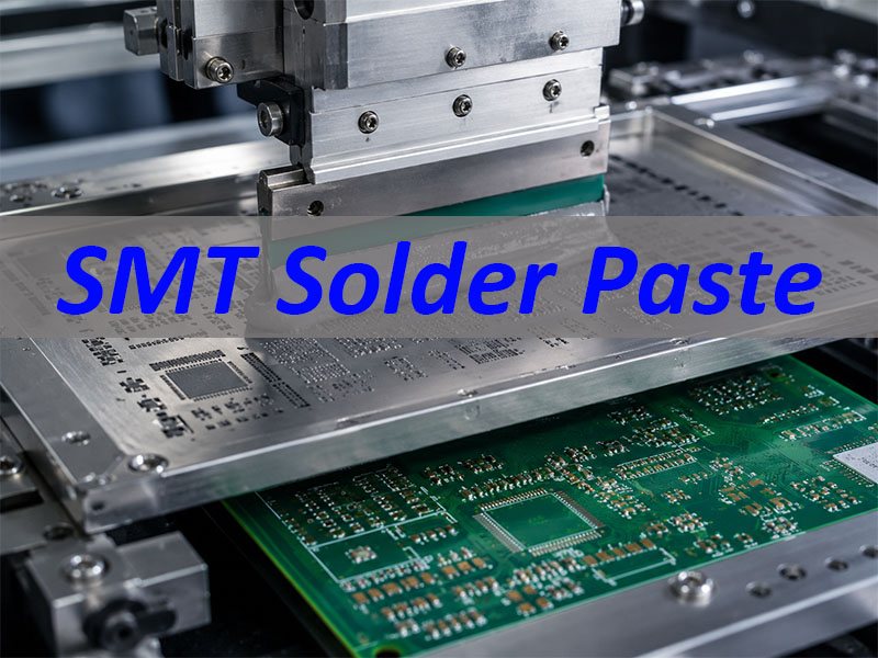
How Does SMT Solder Paste Affect PCBA Assembly Quality?
SMT solder paste is one of the most important process materials in PCBA manufacturing because it directly affects solder joint formation, component stability, reflow performance, and final assembly reliability. A good SMT result does not come from solder paste alone, but from the right paste selection, controlled storage, accurate stencil printing, SPI inspection, reflow profiling, and continuous process control.
Best Technology provides PCB manufacturing, component sourcing, SMT assembly, through-hole assembly, inspection, testing, and traceable PCBA production support for customers in medical, industrial control, automotive electronics, communication, lighting, UAV, and other electronic fields. If you are evaluating a PCBA project and want to check solder paste process feasibility, you can send your Gerber, BOM, assembly drawing, or test requirements to sales@vn.danyupcbs.com for engineering review.
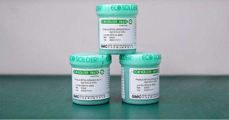
What Is SMT Solder Paste?
SMT solder paste is a printable soldering material used to connect surface-mount components to PCB pads during reflow soldering. It looks like a thick grey paste, but its quality and handling have a strong influence on assembly yield.
In SMT assembly, solder paste performs several functions:
- Provides solder alloy for the joint
The metal powder melts during reflow and forms the final electrical and mechanical connection between the component lead and PCB pad. - Holds components before reflow
The paste has tackiness, which helps keep small parts in place after placement and before the board enters the reflow oven. - Supports wetting during soldering
The flux inside the paste removes light surface oxidation and helps molten solder spread properly on pads and terminals. - Affects defect rate directly
Poor paste condition, wrong printing thickness, stencil mismatch, or unstable reflow settings can lead to solder balls, bridging, tombstoning, voiding, insufficient solder, or open joints.
For buyers, SMT solder paste may look like a small detail. For an SMT factory, it is a core process variable. At Best Technology, solder paste control is connected with DFM review, stencil design, SPI inspection, reflow profiling, AOI, X-ray inspection when needed, and MES-based production traceability.
What Is the Composition of Solder Paste in SMT?
Solder paste is mainly made of solder alloy powder and flux. The alloy forms the solder joint, while the flux supports printing, oxidation removal, wetting, and soldering stability.
A typical SMT solder paste includes:
| Main Part | Function |
|---|---|
| Solder alloy powder | Forms the final solder joint after reflow |
| Flux | Improves wetting and removes light oxidation |
| Solvent | Helps control viscosity and printing behavior |
| Resin or activator | Supports solderability and residue behavior |
| Additives | Adjust tackiness, slump resistance, and storage stability |
The most important composition factors include:
- Alloy type
Common lead-free alloys include SAC305 and similar Sn-Ag-Cu formulas. Some legacy or special projects may still require Sn63Pb37, depending on regulation, product requirement, or customer specification. - Powder particle size
Solder paste powder is often classified by type, such as Type 3, Type 4, or Type 5. Fine-pitch ICs, small passive components, and micro-BGA packages usually need smaller powder sizes for better aperture release. - Flux chemistry
No-clean flux is widely used in modern SMT assembly. Water-soluble flux may be selected when stronger cleaning is required, but it needs a proper cleaning process after soldering. - Viscosity and tackiness
Paste must be thick enough to stay on pads, but printable enough to pass cleanly through stencil apertures. Poor viscosity control can cause incomplete deposits or paste smearing. - Metal content
Higher metal content usually affects print definition, slump behavior, and solder volume. The right value depends on stencil design, component pitch, and process window.
Best Technology reviews solder paste requirements together with pad size, component package, stencil thickness, board surface finish, and reflow profile. This helps customers avoid choosing paste only by brand or alloy name while ignoring the real SMT assembly condition.
What Types of Solder Paste Are Used in SMT?
Different SMT solder paste types are used for different assembly requirements. The right choice depends on component pitch, product reliability level, operating environment, cleaning requirement, and applicable compliance standards.
Common SMT solder paste types include:
- Lead-free solder paste
This is widely used for RoHS-compliant electronics. It is common in industrial control, communication devices, LED products, consumer electronics, automotive modules, and medical electronic assemblies. - Lead-based solder paste
Sn63Pb37 paste has a lower melting point and stable soldering behavior. It may still appear in certain legacy, repair, aerospace, research, or customer-specified applications, but compliance must be confirmed before use. - No-clean solder paste
This is the standard choice for many PCBA projects. It leaves limited residue after reflow and usually does not require post-solder cleaning when the process is controlled properly. - Water-soluble solder paste
This paste provides strong flux activity and good solderability for some difficult surfaces. It requires cleaning after reflow to remove ionic residue. - Low-temperature solder paste
This paste is used when components, connectors, flexible circuits, or substrates cannot tolerate high reflow temperatures. It is useful for selected FPC, LED, sensor, and heat-sensitive assembly projects. - Fine-pitch solder paste
Type 4 or Type 5 solder paste is often selected for dense SMT layouts, QFN, BGA, 0201, 01005, or other fine-aperture stencil designs.
A simple selection view:
| Application Need | Common Paste Direction |
|---|---|
| Standard RoHS PCBA | Lead-free no-clean paste |
| Fine-pitch SMT assembly | Type 4 or finer powder paste |
| Heat-sensitive components | Low-temperature solder paste |
| Strong cleaning requirement | Water-soluble paste |
| Legacy specification | Lead-based paste if allowed |
Best Technology supports SMT assembly for different board and product structures, including rigid FR4 PCB, high-Tg PCB, HDI PCB, aluminum PCB, copper substrate PCB, ceramic PCB, flexible PCB, rigid-flex PCB, and mixed-technology PCBA. The solder paste choice is matched with the assembly process instead of being treated as a fixed material for every project.
How Do SMT Factories Prepare Solder Paste Before Printing?
Solder paste preparation is a small step with large impact. Even a high-quality paste can create defects if it is printed while too cold, expired, poorly mixed, contaminated, or exposed for too long.
Before printing, SMT factories usually control these points:
- Storage temperature
Most solder paste is stored in a refrigerated condition according to the supplier’s datasheet. The goal is to slow chemical activity and maintain stable viscosity. - Shelf life and lot control
Paste should be used within its valid shelf life. Lot number, opening time, usage time, and storage condition should be traceable. - Room-temperature recovery
Paste normally needs to return to room temperature before opening. Opening a cold jar too early can create condensation, which may affect soldering quality. - Mixing before use
Proper mixing helps restore uniform consistency. Over-mixing or poor mixing can both affect printing behavior. - Stencil life control
Once solder paste is on the stencil, exposure time must be controlled. Long exposure can change viscosity and increase printing instability. - Avoiding contamination
Used paste should not be mixed carelessly with fresh paste. Contaminated paste may introduce particles, dry residues, or unstable flux behavior. - First-in, first-out management
FIFO control helps prevent expired or older paste from being used after newer material.
For production-quality SMT assembly, paste preparation should not depend only on operator memory. Best Technology uses controlled production procedures and traceability practices to manage materials, process records, inspection data, and production flow. For medical and high-reliability projects, this process discipline is especially important.
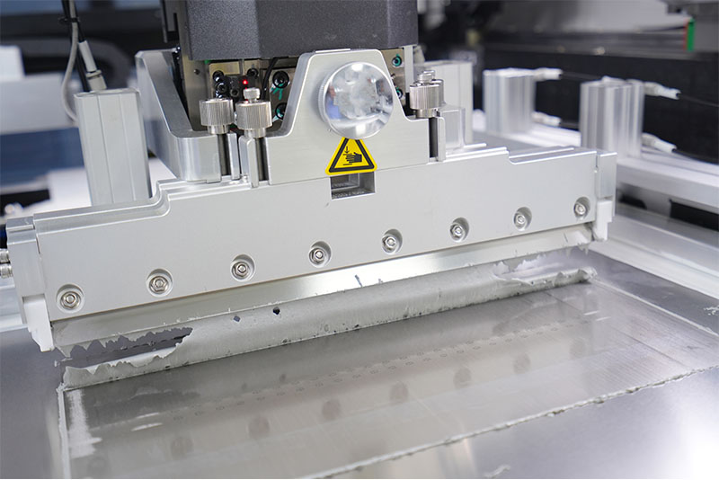
How Does the SMT Solder Paste Printing Process Work?
The SMT solder paste printing process transfers paste onto PCB pads through a stencil. This step determines the solder volume before component placement, so it has a strong effect on solder joint quality.
The basic process is:
- PCB loading and positioning
The bare PCB is loaded into the solder paste printer. The machine aligns the board with fiducial marks to ensure print accuracy. - Stencil alignment
The stencil openings must match the PCB pads. Poor alignment may cause offset deposits, bridging, or insufficient solder. - Squeegee printing
A squeegee blade pushes solder paste across the stencil surface. Paste fills the apertures and is deposited on PCB pads. - Stencil separation
The PCB separates from the stencil. Clean release is critical, especially for fine-pitch components. - Visual check or SPI inspection
The printed board is checked before placement. For higher-quality control, 3D SPI measures paste height, area, volume, and offset. - Component placement
Components are placed into the printed solder paste by SMT placement machines. - Reflow soldering
The paste melts in the reflow oven and forms solder joints after cooling.
Important printing parameters include:
- Stencil thickness
Thicker stencils provide more solder volume, but they may not suit fine-pitch ICs. Thin stencils improve fine-pitch control but may reduce solder volume for larger pads. - Aperture design
The aperture shape affects paste release. Modified openings can reduce bridging, solder balls, and tombstoning. - Squeegee pressure
Too much pressure can scoop paste from apertures. Too little pressure can leave incomplete filling. - Print speed
Speed affects how well paste rolls and fills stencil apertures. Dense boards usually need more controlled printing settings. - Separation speed
Fine-pitch and small aperture designs need stable separation to avoid poor paste release. - Board support
Insufficient support can cause board warpage during printing, leading to uneven paste deposits.
Best Technology treats solder paste printing as a controlled manufacturing step, not a simple front-end operation. For customer projects, our engineering team can review pad design, component package, stencil thickness, and process risks before production to improve first-pass yield.
How Do SMT Solder Paste Stencils and Printers Affect Printing Quality?
Stencil and printer settings decide how accurately solder paste is deposited on the PCB. In many SMT defects, the root cause starts at printing rather than placement or reflow.
Key stencil factors include:
- Stencil thickness
Standard SMT projects may use common stencil thicknesses, while fine-pitch, BGA, QFN, LED, connector, or mixed-size boards may need special thickness evaluation. - Aperture size
Apertures should not always copy pad size exactly. Reduction, expansion, home-plate design, rounded corners, or windowpane patterns may be used depending on the package. - Area ratio
A small aperture with a thick stencil may release paste poorly. Area ratio is important for fine-pitch and small component assembly. - Stencil material and finish
Laser-cut stainless steel stencils are common. Nano-coating may help paste release and reduce cleaning frequency for certain fine-pitch designs. - Step stencil design
Mixed component boards may need different solder volumes in different areas. Step-up or step-down stencils can help balance large terminals and fine-pitch components.
Key printer factors include:
- Alignment accuracy
Accurate fiducial recognition helps keep paste centered on pads. - Squeegee angle and pressure
Stable pressure helps prevent smearing, incomplete filling, or paste scooping. - Underside stencil cleaning
Automatic cleaning helps prevent paste buildup and bridging, especially in fine-pitch areas. - Board clamping and support
Warped or thin boards need proper support to maintain print consistency. - Environmental control
Temperature and humidity affect paste behavior, especially during long production runs.
A useful factory view is simple:
Good stencil design defines the solder volume. Good printing control keeps that volume repeatable.
Best Technology can support stencil optimization for different PCBA structures, including dense SMT boards, LED MCPCB assemblies, ceramic PCB assemblies, rigid-flex assemblies, and high-reliability industrial or medical boards. This is where PCB fabrication knowledge and SMT process experience work together.
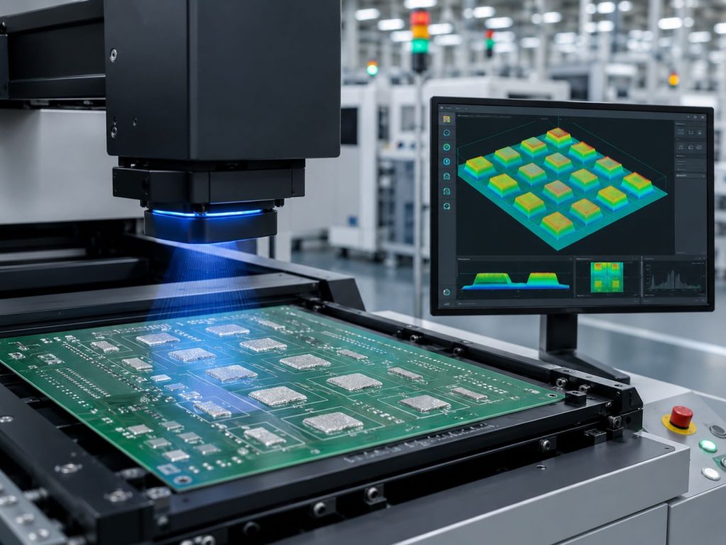
How Do SPI Inspection and Process Control Reduce SMT Solder Paste Defects?
SPI inspection helps detect solder paste problems before components are placed and before defects become more expensive to fix. For modern SMT assembly, especially fine-pitch and high-reliability PCBA, SPI is a key quality gate.
3D SPI can check:
- Paste height
Confirms whether the printed paste is too high or too low. - Paste area
Checks whether the deposit covers the correct pad area. - Paste volume
Helps identify insufficient solder, excessive solder, or unstable deposits. - Paste offset
Finds misalignment between paste and PCB pads. - Bridging risk
Detects paste deposits that may connect adjacent pads. - Missing paste
Finds pads with little or no solder paste before placement.
Common SMT solder paste defects include:
| Defect | Typical Cause |
|---|---|
| Insufficient solder | Poor aperture release, low paste volume, blocked stencil |
| Bridging | Excess paste, poor aperture design, print offset |
| Solder balls | Paste slump, contamination, reflow issue |
| Tombstoning | Uneven wetting, poor paste balance, thermal imbalance |
| Open solder joints | Missing paste, poor wetting, placement issue |
| Voiding | Flux behavior, reflow profile, pad design, component structure |
Process control should include:
- DFM review before production
Check pad design, component spacing, aperture risk, fiducial position, panelization, and thermal balance. - First article inspection
Confirm materials, placement orientation, solder paste deposits, reflow result, and inspection criteria before full production. - SPI data monitoring
Use paste volume and offset data to adjust printing before defects repeat. - AOI after reflow
Check solder joints, polarity, missing parts, wrong parts, tombstoning, bridging, and visible defects. - X-ray inspection when needed
Useful for BGA, QFN, hidden solder joints, voiding analysis, and high-reliability assemblies. - MES traceability
Link production records with material lots, process steps, inspection data, and shipment information.
Best Technology combines DFM, SMT process control, SPI, AOI, X-ray inspection when required, functional testing, and traceable manufacturing records. For medical electronics, industrial control modules, automotive-related assemblies, and communication products, this control helps improve consistency from prototype to batch production.

FAQs About SMT Solder Paste
1. Is SMT solder paste the same as solder wire?
No. SMT solder paste is used for stencil printing and reflow soldering. Solder wire is usually used for hand soldering, rework, or through-hole touch-up.
2. What solder paste is commonly used in SMT assembly?
Lead-free no-clean solder paste is commonly used for RoHS-compliant PCBA manufacturing. Fine-pitch assemblies may require Type 4 or finer powder paste.
3. How long should solder paste return to room temperature before use?
The exact time should follow the solder paste supplier’s datasheet. In production, factories usually control recovery time, opening time, and stencil exposure time to keep printing stable.
4. Why does SMT solder paste need to be mixed before printing?
Mixing helps restore uniform consistency after storage. It supports better rolling behavior, aperture filling, and print repeatability.
5. What happens if solder paste is too cold when opened?
Cold paste can create condensation after opening. Moisture may affect soldering performance and increase process risk.
6. How does stencil thickness affect solder paste printing?
Stencil thickness controls solder volume. Thick stencils provide more paste, while thinner stencils improve control for fine-pitch components. The best choice depends on component mix and pad design.
7. Why is SPI inspection important after solder paste printing?
SPI detects paste volume, height, area, and offset problems before component placement. This helps reduce bridging, insufficient solder, open joints, and repeated process defects.
8. Can one solder paste type be used for every PCBA project?
Not always. Different boards, components, surface finishes, operating conditions, and compliance requirements may need different paste types or process settings.
9. Does solder paste affect BGA and QFN assembly quality?
Yes. BGA and QFN packages have hidden solder joints, so paste volume, stencil design, placement accuracy, and reflow profile must be controlled carefully. X-ray inspection is often used for verification.
10. Can Best Technology help review SMT solder paste and PCBA assembly requirements?
Yes. Best Technology can review your Gerber files, BOM, assembly drawing, soldering requirements, testing requirements, and production notes before PCBA assembly. You can send project files to sales@vn.danyupcbs.com for DFM review, PCB manufacturing, component sourcing, SMT assembly, testing, and traceable production support.