 language
Single-Sided PCB Assembly: Process, Design Tips, Applications, and Manufacturer Guide
Single-sided PCB assembly is important for simple, cost-sensitive electronic products because it helps engineers reduce board complexity, control production cost, and keep the assembly process easier to inspect and repeat. This article explains how single-sided PCB assembly works, when to use it, what design points matter, and how to choose a reliable manufacturing partner.
Best Technology is an experienced PCB and PCBA manufacturer with our own production facilities, including a factory in Vietnam to support customers who need stable local manufacturing, flexible delivery, and smoother supply chain coordination. We provide PCB fabrication, component sourcing, SMT assembly, through-hole assembly, mixed assembly, DFM review, functional testing, and production quality control. With engineering support from prototype to batch production, we help customers build simple and reliable single-sided PCB projects with better cost control and fewer production issues. For project review or quotation support, you can contact our team at sales@vn.danyupcbs.com.
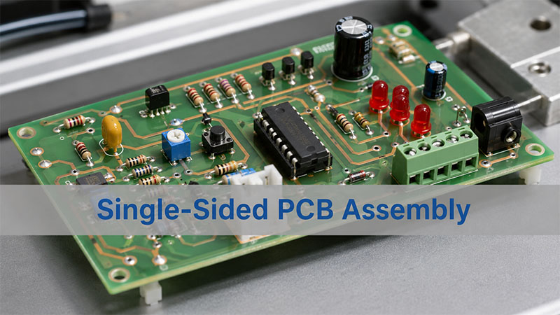
What Is Single-Sided PCB Assembly?
Single-sided PCB assembly means placing and soldering electronic parts on a PCB with copper circuits on one side only. This board type has a simple structure. It usually includes a base material, one copper layer, solder mask, silkscreen, and surface finish.
Because the structure is simple, many engineers use it for basic electronic products. For example, it works well for LED lighting, chargers, small power supplies, home appliances, sensors, remote controls, and simple control boards.
In addition, single-sided boards help reduce cost. They also make production and inspection easier. Therefore, they are a good choice when the circuit does not need many routes or high-speed signals.
However, this does not mean single-sided boards are only for low-end products. With a clean design and proper testing, they can support stable performance in many mature products.
For simple electronic devices, this PCB type often gives a good balance of cost, quality, and delivery speed.
How Does Single Sided PCB Assembly Work?
The single sided PCB assembly process starts with file review. First, the manufacturer checks the Gerber files, BOM, component packages, polarity marks, solder pads, and production notes.
After that, the factory makes the bare PCB. Then, the assembly team places the components and solders them to the copper pads.
For SMT assembly, the process usually includes solder paste printing, component placement, reflow soldering, AOI inspection, and functional testing.
For through-hole assembly, the team inserts parts into holes. Next, the board goes through wave soldering or selective soldering. In some cases, workers also use manual soldering for large parts or special parts.
Many single-sided boards use mixed assembly. For example, one board may use SMD resistors and capacitors. At the same time, it may also use through-hole connectors, terminals, or transformers.
Therefore, a good factory should not only follow the files. It should also check the design before production. This early review can help prevent solder defects, wrong parts, and delays.
What Materials Are Used in Single-Sided PCB Assembly?
Material choice depends on the product function, cost target, heat level, and working environment. In most cases, single-sided boards use FR4, CEM-1, CEM-3, or aluminum substrate.
| Material | Main Feature | Common Use |
|---|---|---|
| FR4 | Strong and stable | Control boards, chargers, consumer products |
| CEM-1 | Low cost | Simple household electronics |
| CEM-3 | Good cost control | Basic electronic modules |
| Aluminum PCB | Better heat transfer | LED lighting and power boards |
| Copper Foil | Forms the circuit path | Current and signal connection |
| Solder Mask | Protects copper traces | Reduces solder bridges |
| Surface Finish | Protects pads | Improves soldering quality |
FR4 is a common choice for many products. It offers good strength and stable insulation. Also, it works well for many control boards and general electronic devices.
Aluminum PCB is better for heat-sensitive products. For example, LED modules and power boards often need aluminum substrates. As a result, heat can move away from the components faster.
Copper thickness also matters. Standard boards often use 1 oz copper. However, high-current products may need 2 oz copper or more.
Surface finish also affects soldering. HASL works well for many cost-sensitive projects. OSP gives a flat surface for SMT. In addition, ENIG offers better flatness and longer storage life.
What Components Are Suitable for Single-Sided PCB Assembly?
Single-sided boards can support many common electronic parts. However, they work best with simple circuits and medium or low component density.
Common parts include resistors, capacitors, diodes, LEDs, transistors, MOSFETs, connectors, terminals, switches, relays, buzzers, inductors, transformers, and simple ICs.
SMD parts help save space. Also, they support faster production. Through-hole parts offer stronger mechanical support. Therefore, connectors, terminals, relays, large capacitors, and transformers often use through-hole packages.
The designer should match the component package with the board structure. For example, a simple LED driver board can use a single-sided PCB. However, a dense communication module may need a double-sided or multilayer PCB.
Placement also needs care. LEDs, diodes, electrolytic capacitors, and ICs need clear polarity marks. As a result, workers and inspection systems can find mistakes faster.
In addition, the assembly partner should check the BOM before production. The team should confirm package size, part direction, soldering method, and possible replacement parts.
When Should You Choose Single-Sided PCB Assembly?
You should choose single-sided PCB assembly when your circuit has a simple layout. It also fits products with limited routing needs.
This board type works well for products that need stable function without a complex PCB structure.
| Product Type | Why It Fits |
|---|---|
| LED lighting boards | Simple circuit and good cost control |
| Power adapter boards | Clear layout and stable production |
| Home appliance boards | Mature design and repeat orders |
| Sensor modules | Simple signal path |
| Remote controls | Low component density |
| Relay control boards | Easy inspection and testing |
| Small display boards | Simple connection structure |
| Educational electronics | Easy to build and repair |
In addition, single-sided boards help during early product tests. Engineers can test simple functions faster. They can also control prototype cost.
For mass production, this structure can reduce bare PCB cost. It can also make inspection easier. Therefore, it works well for stable repeat orders.
However, engineers should not force a complex circuit into one copper layer. If the layout needs too many jumper wires, tight spacing, or long routes, a double-sided PCB may work better.
So, the best choice depends on circuit complexity, current level, board size, test needs, and long-term production goals.
Single-Sided PCB Assembly vs Double-Sided PCB Assembly: What Is the Difference?
Single-sided PCB assembly uses one copper layer. Double-sided PCB assembly uses copper on both sides. Vias connect the top and bottom circuits.
Because of this, double-sided boards give engineers more routing space. However, they also cost more than single-sided boards.
| Item | Single-Sided PCB Assembly | Double-Sided PCB Assembly |
|---|---|---|
| Copper Layer | One side | Two sides |
| Routing Space | Limited | More flexible |
| Component Density | Low to medium | Medium to high |
| PCB Cost | Lower | Higher |
| Layout Difficulty | Easier | More flexible |
| Inspection | Easier | More detailed |
| Best For | Simple products | More complex products |
Single-sided boards suit simple products with clear current paths. They help reduce cost and speed up production.
On the other hand, double-sided boards suit products with more parts or tighter space. They also help shorten signal paths and improve layout quality.
However, engineers should compare the total project cost, not only the PCB price. For example, a single-sided board may look cheaper. But too many jumper wires can add labor cost.
In many cases, a double-sided board may cost more at first. However, it can make assembly easier and more stable.
Therefore, a DFM review can help you choose the better structure.
What Are the Design Rules for Single-Sided PCB Assembly?
Good design makes single-sided assembly easier. It also improves product quality. Since the board has only one copper layer, engineers should plan each trace with care.
Keep the layout simple.
First, place related parts close together. Put input parts near the connector. Also, keep power parts close to the power path. A clean layout can reduce routing problems.
Use the right trace width.
High-current lines need wider traces. For example, LED boards, relay boards, and power boards need extra attention here. As a result, the board can handle current more safely.
Leave enough spacing.
Good spacing reduces solder bridges. It also helps AOI and visual inspection.
Avoid too many jumper wires.
A few jumper wires may work. However, too many jumpers add labor and increase error risk. In that case, a double-sided PCB may be better.
Mark polarity clearly.
LEDs, diodes, ICs, and electrolytic capacitors need clear marks. Therefore, good silkscreen helps the assembly team avoid mistakes.
Add useful test points.
Test points help the factory check voltage, current, ground, signal nodes, and output function. In addition, they make repair and failure analysis easier.
Check mechanical fit.
Mounting holes, connectors, board edges, and housing space should match the final product. Otherwise, the board may pass electrical testing but fail during final assembly.
These rules look simple. However, they strongly affect production yield. Therefore, a professional single sided PCB assembly manufacturer should review these details before mass production.
How Is Single-Sided PCB Assembly Tested for Quality?
Testing helps confirm that the board works as expected. Even simple PCB assemblies need careful inspection.
Most factories use visual inspection, AOI, electrical testing, and functional testing. However, the exact test method depends on the product and customer requirements.
| Test Method | What It Checks |
|---|---|
| Visual Inspection | Solder joints, missing parts, wrong direction |
| AOI | Component position, solder bridge, low solder |
| ICT | Open circuits, shorts, resistance, capacitance |
| Functional Test | Real working performance |
| Power-On Test | Voltage, current, LED status, relay action |
| Aging Test | Long-time working stability |
| Final QC | Appearance, label, packing, and quantity |
For simple products, AOI and functional testing often provide enough control. However, power products, LED modules, and industrial boards may need extra tests.
Before production, the customer should confirm the test plan. This plan should include test items, pass limits, fixture needs, sample rate, and test records.
In addition, traceability matters. The manufacturer should keep records for PCB batches, component lots, production dates, inspection results, and shipment details.
Good testing does more than find defects. It also helps the factory improve future production.
How Much Does Single-Sided PCB Assembly Cost?
Single-sided PCB assembly usually costs less than double-sided or multilayer assembly. The simple board structure helps reduce material cost and PCB fabrication cost.
However, the final cost still depends on many factors.
Key cost factors include PCB size, material type, copper thickness, surface finish, component count, soldering method, test needs, order quantity, and delivery time.
For example, a small FR4 board with common SMD parts usually costs less. However, an aluminum LED board with high-power LEDs, thicker copper, and aging tests will cost more.
Component sourcing also affects cost. Stable and common parts help control the budget. On the other hand, rare parts, obsolete parts, or urgent sourcing can increase cost and lead time.
Testing cost also changes by product type. A simple power-on test may cost less. However, a custom functional test fixture needs more preparation.
Therefore, the best way to control cost is to start with a DFM and BOM review. A good manufacturer can suggest better panel design, suitable materials, common part packages, and practical test methods.
As a result, you can reduce waste and keep production more stable.
How to Choose a Reliable Single Sided PCB Assembly Manufacturer?
A reliable single sided PCB assembly manufacturer should offer more than soldering. It should help you review the design, source parts, control quality, and manage delivery.
- First, check engineering support. The manufacturer should review Gerber files, BOM, pad design, polarity marks, soldering method, and test points before production.
- Next, check production capability. A good partner should support PCB fabrication, SMT assembly, through-hole assembly, mixed assembly, AOI inspection, and functional testing.
- Also, check component sourcing support. The supplier should confirm part availability and suggest replacement parts when needed.
If you need China single-side pcb assembly, choose a partner with clear communication and export experience. Price matters. However, stable quality matters more for repeat orders.
Best Technology supports PCB fabrication, component sourcing, SMT assembly, through-hole assembly, mixed assembly, testing, and production quality control.
In addition, our engineering team can review your files before production. We can also help improve the design for easier manufacturing.
If you have a single-sided PCB project, you can send your Gerber files and BOM to sales@vn.danyupcbs.com. Our team will review your project and offer practical manufacturing suggestions.
To wrap up, single-sided PCB assembly remains a smart choice for many simple electronic products. It helps control cost, simplify production, and speed up delivery.
This board type works well for LED products, control boards, chargers, sensors, remote controls, and basic power modules. Also, it gives strong value when the circuit layout stays simple and clean.
However, good design still matters. Engineers should control trace width, spacing, component placement, polarity marks, and test points from the beginning.
In addition, the right manufacturer can make production smoother. With DFM review, stable component sourcing, controlled assembly, and functional testing, your project can move from prototype to batch production with less risk.
Best Technology can support your project from PCB fabrication to complete assembly. For quotations or engineering review, contact us at sales@vn.danyupcbs.com.