 language
How to Read Chip Resistor Values?
Do you often struggle to interpret the tiny markings on surface mount resistors, or find yourself unsure if you’re reading the correct resistance for your circuit? Understanding how to read chip resistor values is essential for ensuring circuit accuracy, avoiding component waste, and streamlining your workflow. This guide breaks down everything you need to know, from basic definitions to practical troubleshooting, so you can confidently work with these essential components every day.

What is a Chip Resistor?
A chip resistor is a small, rectangular passive component designed to limit electric current flow in electronic circuits. Unlike through-hole resistors, it has no leads and is directly mounted on the surface of a printed circuit board using surface mount technology. This compact design makes it ideal for modern, miniaturized electronics where space is at a premium.
Most chip resistors feature a ceramic substrate, a resistive layer, and metal end electrodes. The resistive layer determines the component’s resistance value, while the end electrodes ensure reliable soldering to the PCB. These components are mass-produced to meet standard specifications, making them consistent and interchangeable across different manufacturers and applications.
What Do Chip Resistors Do?
Chip resistors perform a range of critical functions in electronic circuits, acting as foundational components that ensure devices operate safely and efficiently. Below is a detailed breakdown of their key roles.
- Limit electric current: They restrict the amount of current flowing through a circuit, preventing damage to sensitive components like microchips and capacitors. This is critical for maintaining safe operating conditions and extending the lifespan of electronic devices.
- Divide voltage: They create voltage drops across different parts of a circuit, allowing for precise control of voltage levels in specific components. This is essential for powering components that require different voltage inputs to function correctly.
- Terminate signals: They absorb excess signal energy in high-frequency circuits, reducing signal reflections and ensuring stable performance. This is particularly important in communication devices and digital electronics.
- Adjust circuit gain: They fine-tune the gain of amplifiers and other signal-processing components, ensuring consistent performance across different operating conditions.
- Protect circuits: They act as a safety measure by limiting current in the event of a short circuit, preventing overheating and potential device failure.
What Are Chip Resistors Used for?
Given their compact size and versatile functionality, chip resistors are integrated into nearly all modern electronic devices across various industries. Here are their most common application areas.
- Consumer electronics: Found in smartphones, laptops, tablets, televisions, and wearables. Their small size makes them perfect for compact devices, where they regulate current and voltage in power management circuits.
- Automotive electronics: Used in engine control units, infotainment systems, and safety features like airbags. These components must meet strict reliability standards to withstand extreme temperatures and vibration.
- Medical devices: Integrated into diagnostic equipment, monitors, and portable medical tools. High-precision variants ensure accurate readings and stable performance in critical healthcare applications.
- Industrial equipment: Used in programmable logic controllers, sensors, and power supplies. Industrial-grade options are designed to resist harsh environments, including high humidity and chemical exposure.
- Telecommunications: Found in routers, modems, and cellular base stations. They help regulate signal strength and reduce interference in high-frequency communication circuits.
What Are Types of Chip Resistor?
Chip resistors come in several types, each designed to meet specific performance, precision, and environmental requirements. Understanding these types helps in selecting the right component for your application.
- Thick film chip resistors: The most common type, accounting for over 90% of the market. They use a thick resistive paste printed on a ceramic substrate, offering cost-effectiveness and a wide range of resistance values. They are ideal for general-purpose applications with moderate precision requirements.
- Thin film chip resistors: Manufactured using a thin layer of metal alloy deposited on a ceramic substrate via vacuum sputtering. They offer higher precision, lower noise, and better temperature stability than thick film variants, making them suitable for medical, aerospace, and precision instrumentation applications.
- Current sense chip resistors: Designed for low resistance values (milliohm range) to measure current flow in circuits. They feature low temperature coefficients and high power ratings, making them essential for battery management systems and power monitoring applications.
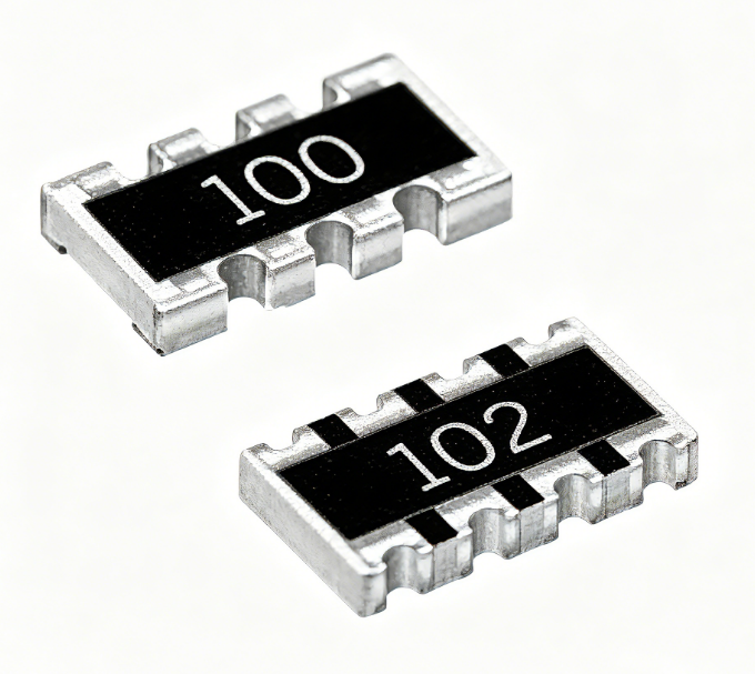
- Chip resistor arrays: Multiple resistors integrated into a single package, saving space and simplifying PCB assembly. They are commonly used in digital circuits where multiple identical resistors are required, such as in bus lines and pull-up/pull-down circuits.
- Anti-sulfur chip resistors: Equipped with special electrodes to resist sulfide corrosion, which can cause resistance drift and component failure. They are ideal for industrial and automotive applications where exposure to sulfur-containing gases is common.
Chip Resistor Datasheet
A chip resistor datasheet is a technical document that provides all essential specifications of the component. Knowing how to read and interpret its sections is key to proper component selection and usage.
| Item | Specifications |
| Parasitic Inductance | Typically 0.1~0.5nH for standard types, ≤0.05nH for high-frequency models |
| Parasitic Capacitance | ≤0.5pF for thin film resistors, 1~2pF for standard thick film resistors |
| Sulfur Resistance Level | Grade 1 (no sulfur resistance), Grade 2 (IEC 60664-1 compliant), Grade 3 (high sulfur resistance for harsh environments) |
| Humidity Coefficient of Resistance (HCR) | ≤±0.1%/RH for precision models, ≤±0.3%/RH for standard thick film resistors |
| Thermal Shock Resistance | -55°C to +155°C, 100 cycles, resistance change ≤±0.5% (standard); -65°C to +175°C, 200 cycles for automotive grade |
| Solderability Compliance | IPC/JEDEC J-STD-002, solder coverage ≥95% after 10 seconds at 260°C |
| Storage Temperature Range | -55°C~+155°C (standard), -65°C~+175°C (automotive/industrial grade), 12 months storage in dry environment (≤60% RH) |
| Resistance Stability Over Time | ≤±0.1% after 1000 hours at 70°C (precision thin film), ≤±0.5% after 1000 hours (standard thick film) |
| Voltage Coefficient of Resistance (VCR) | ≤10ppm/V for thin film, ≤50ppm/V for thick film, ≤100ppm/V for general-purpose models |
| Packaging Type & Quantity | Tape & Reel: 1000pcs/reel (0201/0402), 5000pcs/reel (0603/0805), 2000pcs/reel (1206/1210); Tube: 100pcs/tube, 500pcs/tube |
What Are Common Chip Resistor SMD Sizes?
SMD chip resistors are available in standard sizes, which correspond to their physical dimensions and rated power. Choosing the right size is crucial for PCB space management and circuit performance.
| SMD Size (Imperial) | SMD Size (Metric) | Rated Power (70°C) | Typical Applications |
| 0201 | 0603 (0.6mm x 0.3mm) | 1/20W (0.05W) | Wearables, smartphones, ultra-compact consumer electronics |
| 0402 | 1005 (1.0mm x 0.5mm) | 1/16W (0.0625W) | Tablets, cameras, small digital devices |
| 0603 | 1608 (1.6mm x 0.8mm) | 1/10W (0.1W) | General-purpose consumer electronics, laptops, routers |
| 0805 | 2012 (2.0mm x 1.25mm) | 1/8W (0.125W) | Power supplies, industrial sensors, automotive infotainment |
| 1206 | 3216 (3.2mm x 1.6mm) | 1/4W (0.25W) | Industrial equipment, automotive control units, power amplifiers |
| 1210 | 3225 (3.2mm x 2.5mm) | 1/2W (0.5W) | High-power circuits, heavy-duty industrial applications |
How to Determine Resistance for Chip Resistors?
Accurately determining the resistance of a chip resistor is essential for circuit troubleshooting and assembly. There are several reliable methods to identify or calculate this key value.
- Check the surface markings: Most chip resistors have printed codes (digital or alphanumeric) that indicate their resistance value. These codes are the fastest and most common way to determine resistance without specialized equipment.
- Use a digital multimeter: Set the multimeter to the resistance measurement mode (ohms), touch the probes to the two end electrodes of the chip resistor, and read the displayed value. This method is accurate and ideal for verifying markings or testing for faulty components.
- Refer to the datasheet: If the chip resistor has no visible markings or the markings are unclear, locate the part number on the component or packaging and look up the datasheet for the specified resistance value.
- Use a resistor color code chart (for larger variants): Some larger chip resistors may use color bands instead of digital codes. Match the color bands to a standard chart to determine the resistance value and tolerance.
- Calculate using circuit values: If the chip resistor is installed in a circuit, use Ohm’s Law (V = IR) to calculate resistance by measuring the voltage drop across the component and the current flowing through it.
How to Read Chip Resistor Values?
Chip resistors use specific marking codes to indicate their resistance values, with different code types for standard, high, and ultra-high precision components. Learning to read these codes simplifies component identification.
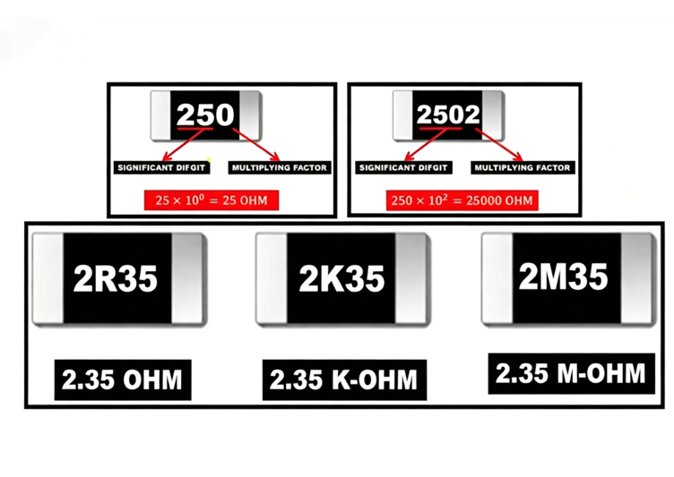
- Three-digit code: The most common marking for standard-precision chip resistors. The first two digits are the significant figures, and the third digit is the multiplier (10 raised to the power of the third digit). For example, a code of 103 means 10 x 10³ = 10,000 ohms (10kΩ).
- Four-digit code: Used for high-precision chip resistors. The first three digits are the significant figures, and the fourth digit is the multiplier. For example, a code of 1002 means 100 x 10² = 10,000 ohms (10kΩ).
- EIA-96 alphanumeric code: Used for ultra-high-precision chip resistors. It consists of two digits and one letter. The two digits correspond to a value from the EIA-96 standard table, and the letter is the multiplier. For example, a code of 18C means 150 x 10² = 15,000 ohms (15kΩ).
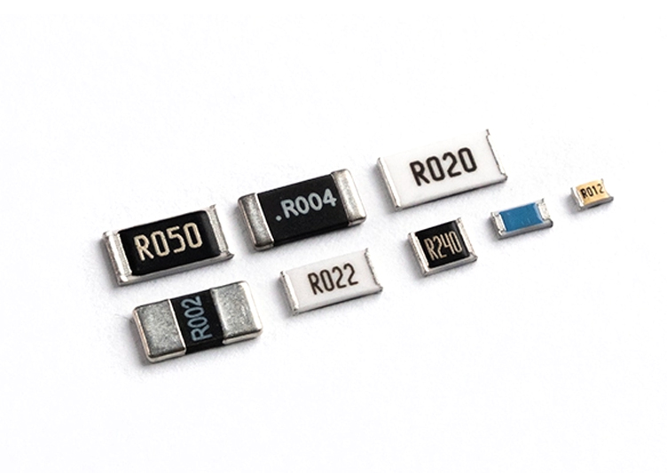
- R-for-decimal code: Used for low-resistance chip resistors (below 10 ohms). The letter R represents the decimal point. For example, a code of 4R7 means 4.7 ohms, and R22 means 0.22 ohms.
- Zero-ohm code: Marked as 000 or 0R, these chip resistors act as jumpers or short circuits. They have a resistance value of approximately 0 ohms and are used to connect different parts of a circuit without adding resistance.
How to Read Chip Resistor Code & Markings?
Reading chip resistor codes and markings involves more than just interpreting numbers—you must also identify the code type, apply multipliers, and account for tolerance. This step-by-step guide simplifies the process.
- Identify the code type: First, determine if the marking is a three-digit, four-digit, EIA-96, or R-for-decimal code. This is usually apparent from the number of characters and the presence of letters or the letter R.
- Interpret significant figures: For three-digit and four-digit codes, the first two or three digits are the significant figures, respectively. These are the core digits of the resistance value.
- Apply the multiplier: The last digit (for three-digit and four-digit codes) or the letter (for EIA-96 codes) tells you how many times to multiply the significant figures by 10. For EIA-96 codes, refer to a standard EIA-96 table to find the value corresponding to the two digits.
- Account for tolerance: Some chip resistors include a tolerance marking, usually a single letter next to the resistance code. Common tolerance codes are J (±5%), F (±1%), and D (±0.5%).
- Handle unclear markings: If the code is smudged or unreadable, clean the component with a soft cloth and magnifying glass. If still unreadable, use a multimeter to measure the resistance directly.
How to Calculate Chip Resistors?
Calculating chip resistor values involves applying simple formulas to interpret marking codes, as well as calculating combined resistance for resistors in series or parallel configurations.
- Three-digit code calculation: Multiply the first two significant figures by 10 raised to the power of the third digit. Example: 472 = 47 x 10² = 4,700 ohms (4.7kΩ).
- Four-digit code calculation: Multiply the first three significant figures by 10 raised to the power of the fourth digit. Example: 1501 = 150 x 10¹ = 1,500 ohms (1.5kΩ).
- EIA-96 code calculation: Look up the two-digit number in the EIA-96 table to get the significant value, then multiply by the multiplier corresponding to the letter. Example: 01A = 100 x 10⁰ = 100 ohms.
- R-for-decimal calculation: Replace the letter R with a decimal point. Example: 5R6 = 5.6 ohms, R10 = 0.10 ohms.
- Series and parallel calculation: When multiple chip resistors are used in series, add their resistance values together. When in parallel, use the formula 1/Rtotal = 1/R1 + 1/R2 + … + 1/Rn. Example: Two 10kΩ resistors in parallel = 5kΩ.
How to Safely Remove a Chip Resistor?
Removing a chip resistor from a PCB requires careful handling to avoid damaging the component or the board. Following proper steps ensures safe and effective removal for repair or replacement.
- Prepare the workspace: Ensure the circuit is powered off and disconnected from any power source. Use an anti-static mat and wristband to prevent electrostatic damage to sensitive components.
- Gather tools: You will need a hot air station, soldering iron, tweezers, and flux. The hot air station is used to heat the solder joints, while the tweezers are used to remove the component.
- Apply flux: Apply a small amount of flux to the two end electrodes of the chip resistor. Flux helps melt the solder and prevents oxidation during heating.
- Heat the solder joints: Set the hot air station to 300-350°C with low to medium airflow. Direct the hot air nozzle at the end electrodes, moving it back and forth to heat both joints evenly.
- Remove the component: Once the solder has melted, use tweezers to gently lift the chip resistor from the PCB. Be careful not to apply excessive force, as this can damage the PCB pads.
- Clean the PCB: After removing the component, use a soldering iron to remove any excess solder from the PCB pads. Clean the area with isopropyl alcohol to remove flux residue.
What Are the Common Failure Modes of Chip Resistors and How to Avoid Them?
Chip resistors can fail due to various factors, including environmental stress, improper usage, or manufacturing defects. Identifying these failure modes and taking preventive measures extends component lifespan.
- Resistance drift: Occurs when the resistance value changes over time due to temperature fluctuations, humidity, or aging. To avoid this, select chip resistors with a low temperature coefficient and operate them within their rated temperature range.
- Open circuit: Happens when the chip resistor’s resistive layer or electrodes break, resulting in no current flow. Avoid this by not exceeding the component’s rated power or voltage, and using proper soldering techniques to prevent thermal stress.
- Short circuit: Occurs when the end electrodes are bridged by solder or debris, resulting in zero resistance. Prevent this by using clean soldering tools, applying the correct amount of solder, and keeping the PCB free of debris.
- Sulfur corrosion: Affects chip resistors with silver electrodes, causing resistance drift and open circuits. Use anti-sulfur chip resistors in industrial or automotive environments where sulfur-containing gases are present.
- Mechanical damage: Caused by excessive force during installation or removal, resulting in cracked substrates or damaged electrodes. Handle components with care, use proper tools, and avoid bending the PCB.
How to Find Information to Purchase Chip Resistors?
When purchasing chip resistors, it’s important to source accurate product information to ensure the component matches your circuit requirements. Here are reliable ways to find the details you need.
- Check manufacturer websites: Leading manufacturers provide detailed product information, datasheets, and availability. Search for surface mount resistors by specifications like resistance value, tolerance, size, and power rating.
- Use electronic component distributors: Distributors offer a wide range of chip resistors from multiple manufacturers. Filter search results by key specifications to find the exact component you need, and check stock levels and pricing.
- Refer to component databases: Online databases compile datasheets and product information from various manufacturers, making it easy to compare different chip resistor options and find the best fit for your application.
- Consult application notes: Manufacturer application notes provide guidance on selecting the right chip resistor for specific applications, helping you avoid over-specifying or under-specifying components.
- Contact supplier support: If you’re unsure about which chip resistor to purchase, contact the supplier’s technical support team for assistance. They can help you select the correct component based on your circuit requirements.
FAQs About Chip Resistors
Below are answers to the most frequently asked questions about chip resistors, addressing common concerns related to usage, selection, troubleshooting, and interchangeability.
Q1: Can I use a chip resistor with a higher power rating than required?
A1: Yes, you can use a chip resistor with a higher power rating than required. This provides a safety margin and reduces the risk of overheating, especially in circuits with variable current. However, higher power resistors are larger, so ensure there is enough space on the PCB.
Q2: Why do some chip resistors have no markings?
A2: Some very small chip resistors (such as 0201 and 0402 sizes) have no markings due to space constraints. In these cases, you must refer to the component packaging or datasheet to determine the resistance value.
Q3: What is the difference between thick film and thin film chip resistors?
A3: Thick film chip resistors use a thick paste layer for the resistive element, offering lower cost and wider resistance ranges. Thin film chip resistors use a thin metal layer, providing higher precision, lower noise, and better temperature stability.
Q4: How do I test a chip resistor for faults?
A4: Test a chip resistor by measuring its resistance with a digital multimeter. Compare the measured value to the specified value on the datasheet. If the measured value is significantly different (outside the tolerance range), the component is faulty.
Q5: Can chip resistors be used in high-frequency circuits?
A5: Yes, chip resistors can be used in high-frequency circuits. However, you should select variants with low parasitic inductance and capacitance, such as thin film or high-frequency-specific chip resistors, to ensure stable performance.
Q6: What is the maximum operating temperature for chip resistors?
A6: The maximum operating temperature varies by manufacturer and type, but most chip resistors can operate between -55°C and 150°C. Industrial and automotive-grade variants may have higher temperature ratings.
Q7: How do I choose the right size chip resistor for my PCB?
A7: Choose the size based on the required power rating and PCB space. Larger sizes (such as 1206 and 1210) can handle higher power, while smaller sizes (such as 0201 and 0402) are ideal for compact designs.
Q8: Are chip resistors interchangeable between manufacturers?
A8: Yes, chip resistors are interchangeable between manufacturers if they have the same resistance value, tolerance, size, and power rating. Always verify the datasheet to ensure all specifications match.