 language
What is a MLCC Capacitor? MLCC VS Electrolytic VS Tantalum Capacitors
If you work with electronic circuits, you’ve likely encountered MLCC capacitor, but may not know their basics or why they’re preferred over electrolytic or tantalum types. Understanding MLCCs is critical for designing reliable circuits, and this guide covers their key details: structure, size, advantages, applications, comparisons, and practical topics like voltage rating and cost to help you make informed project decisions.
What is a MLCC Capacitor?
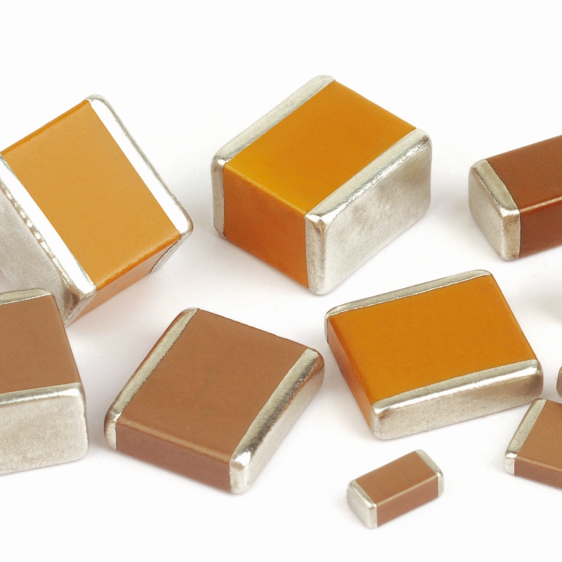
MLCC (Multilayer Ceramic Capacitor) is a passive electronic component that stores and releases electrical energy. It is widely used for its small size, high capacitance density and excellent high-frequency performance. Unlike single-layer ceramic capacitors, it consists of alternating layers of ceramic dielectric and metal electrodes, enabling higher capacitance in a compact form; it is also called a monolithic ceramic capacitor and is commonly used in SMT applications.
MLCCs are categorized by dielectric materials, which determine their performance. The three main types are: Class I (temperature-compensating, e.g., C0G/NP0, with stable capacitance for high-frequency circuits); Class II (high dielectric constant, e.g., X7R, X5R, with higher capacitance but slight drift); Class III (semiconductor, e.g., Y5V, with highest capacitance density but low stability, for non-critical applications like bypassing).
What is the Internal Structure of a MLCC Capacitor?
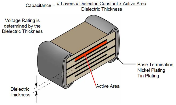
Understanding the MLCC capacitor construction is key to its performance. Its internal structure is precise, consisting of three core components: ceramic dielectric layers, internal electrodes, and external electrodes. A cross-section of an MLCC shows alternating thin ceramic dielectric sheets and metal internal electrodes, bonded together via high-temperature sintering.
Ceramic dielectric layers are made from powdered ceramic materials (e.g., barium titanate) mixed with binders, rolled into ultra-thin sheets (as thin as 1μm). Internal electrodes are printed onto these sheets using conductive pastes (typically nickel or copper for modern MLCCs). The printed sheets are stacked in a staggered pattern, with internal electrodes alternating to connect to the two external electrodes—this stacking creates hundreds or thousands of parallel individual capacitors, multiplying total capacitance.
External electrodes, usually made of copper, nickel, and tin, are applied to the ends of the stacked assembly, serving as circuit board connection points with good solderability and conductivity. The entire assembly is sintered at 1000–1300°C to fuse ceramic layers and internal electrodes into a solid structure, forming the durable, compact MLCC used today.
What Size is a MLCC Capacitor?
MLCC capacitors have standardized surface mount sizes, specified in both imperial (inches) and metric (millimeters). Their size directly affects capacitance, voltage rating, and application suitability. Below is the MLCC capacitor size chart with common sizes, dimensions, and typical capacitance ranges for selection.
| Imperial Size (Length x Width) | Metric Size (mm, Length x Width x Height) | Typical Capacitance Range | Typical Voltage Rating Range | Common Applications |
|---|---|---|---|---|
| 01005 | 0.4 x 0.2 x 0.2 | 0.2pF – 100pF | 6.3V – 25V | TWS earbuds, microcontrollers, ultra-compact devices |
| 0201 | 0.6 x 0.3 x 0.3 | 0.5pF – 1μF | 6.3V – 50V | Smartphones, wearables, small consumer electronics |
| 0402 | 1.0 x 0.5 x 0.5 | 1pF – 10μF | 6.3V – 100V | Tablets, laptops, IoT devices |
| 0603 | 1.6 x 0.8 x 0.8 | 1pF – 47μF | 6.3V – 200V | Industrial controls, automotive infotainment |
| 0805 | 2.0 x 1.25 x 1.25 | 1pF – 100μF | 6.3V – 250V | Power supplies, automotive sensors |
| 1206 | 3.2 x 1.6 x 1.6 | 1pF – 220μF | 6.3V – 500V | Power amplifiers, industrial equipment |
| 2225 | 5.6 x 6.4 x 2.5 | 1μF – 1000μF | 6.3V – 630V | High-power circuits, automotive ECUs |
What Should the Voltage Rating of a MLCC Capacitor Be?
The voltage rating of an MLCC is the maximum voltage it can safely withstand without breakdown. To ensure circuit reliability, select an MLCC with a voltage rating 1.5 to 2 times the circuit’s maximum operating voltage, which accounts for voltage spikes and transient changes.
MLCC voltage ratings range from 4V to 1000V, depending on size and dielectric. Class I MLCCs usually have higher voltage ratings than Class II. Low-voltage MLCCs (4V–25V) are for consumer electronics, while high-voltage ones (100V+) are used in power supplies and industrial equipment.
MLCC Capacitor Datasheet
An MLCC datasheet, provided by manufacturers, details the capacitor’s key specifications and performance. It helps engineers and designers select the right MLCC, and below is a clear breakdown of its critical sections.
| Datasheet Section | Key Information Provided | Why It Matters |
|---|---|---|
| Part Number | Unique identifier for the MLCC capacitor, including size, capacitance, voltage, and dielectric type | Ensures you order the correct component |
| Capacitance | Nominal capacitance value, capacitance tolerance (e.g., ±5%, ±10%), and capacitance vs. temperature characteristics | Determines if the capacitor can store the required amount of energy |
| Voltage Rating | DC rated voltage, AC voltage tolerance, and breakdown voltage | Prevents capacitor failure due to overvoltage |
| Dielectric Material | Class (I/II/III), material code (e.g., C0G, X7R, Y5V), and temperature coefficient | Affects capacitance stability, temperature range, and frequency performance |
| Dimensions | Imperial/metric size, height, and lead pitch (if applicable) | Ensures the capacitor fits on the circuit board |
| ESR (Equivalent Series Resistance) | Typical and maximum ESR at specific frequencies (e.g., 100kHz) | Impacts power loss and high-frequency performance |
| Operating Temperature Range | Minimum and maximum temperature the capacitor can operate in (e.g., -55°C to +125°C) | Ensures compatibility with the application environment |
| Reliability Data | MTBF (Mean Time Between Failures), shelf life, and endurance testing results | Indicates the capacitor’s long-term performance and durability |
What are the Advantages of MLCCs?
MLCCs offer numerous advantages that make them the preferred choice for most modern electronic applications. These advantages address key pain points for designers, including size, performance, and reliability.
- Small Size and High Capacitance Density: MLCCs are extremely compact, with sizes as small as 01005 (0.4×0.2mm). Their layered structure allows them to achieve high capacitance in a tiny form factor, making them ideal for compact devices like smartphones, wearables, and IoT sensors.
- Excellent High-Frequency Performance: MLCCs have low equivalent series resistance (ESR) and equivalent series inductance (ESL), which makes them highly efficient at high frequencies (up to GHz range). This makes them perfect for RF circuits, power supplies, and high-speed data transmission systems.
- Long Lifespan and High Reliability: Unlike electrolytic capacitors, MLCCs have no liquid electrolyte, so they are not prone to leakage or drying out. They can operate for tens of thousands of hours without performance degradation, making them suitable for long-life applications like automotive electronics and industrial equipment.
- Wide Temperature Range: Most MLCCs operate reliably between -55°C and +125°C, with some industrial-grade models capable of withstanding temperatures up to +150°C. This makes them suitable for harsh environments like automotive underhood applications and industrial control systems.
- Low Power Loss: The low ESR of MLCCs results in minimal power loss, which improves the efficiency of the circuit. This is especially important in battery-powered devices, where reducing power consumption extends battery life.
- Cost-Effective: For most capacitance and voltage ranges, MLCCs are more affordable than tantalum or polymer capacitors, making them a cost-effective choice for high-volume production.
What are the Disadvantages of MLCCs?
While MLCCs offer many advantages, they also have some limitations that designers need to consider when selecting components.
- Voltage-Dependent Capacitance: Class II and Class III MLCCs (X7R, X5R, Y5V) experience capacitance drift when exposed to high voltages. This can be a problem in applications where capacitance stability is critical, such as precision timing circuits.
- Limited Capacitance Range: While MLCCs offer high capacitance density, they are not available in extremely high capacitance values (above 1000μF) like electrolytic capacitors. For applications requiring very high capacitance, you may need to use a combination of MLCCs and electrolytic capacitors.
- Brittleness: MLCCs are made of ceramic material, which is brittle. They can crack or break if subjected to excessive mechanical stress, such as during soldering, handling, or vibration. This is a concern in automotive and industrial applications where vibration is common.
- Humidity Sensitivity: Some MLCCs are sensitive to humidity, which can degrade their performance over time. This is especially true for high-voltage MLCCs, which may require hermetic sealing to protect against moisture.
- Noise Generation: Under certain conditions, MLCCs can generate audible noise (called piezoelectric noise) due to the expansion and contraction of the ceramic material when subjected to AC voltage. This can be a problem in audio equipment or other noise-sensitive applications.
What are MLCC Capacitors Used for?
MLCC capacitors are used in almost every electronic device, thanks to their versatility, small size, and high performance. Below are the most common applications, organized by industry, to help you understand where MLCCs add value.
- Consumer Electronics: This is the largest market for MLCCs. They are used in smartphones, tablets, laptops, TWS earbuds, smartwatches, and TVs. In these devices, MLCCs serve as bypass capacitors (to filter out noise from power supplies), coupling capacitors (to transfer AC signals between circuits), and decoupling capacitors (to stabilize voltage for microprocessors and chips).
- Automotive Electronics: MLCCs are critical in modern vehicles, where they are used in engine control units (ECUs), battery management systems (BMS), infotainment systems, and advanced driver assistance systems (ADAS). Automotive-grade MLCCs are designed to withstand high temperatures, vibration, and harsh environments, with ratings like AEC-Q200 to ensure reliability.
- Industrial Equipment: In industrial control systems, PLCs, frequency converters, and power supplies, MLCCs are used for filtering, decoupling, and voltage stabilization. Industrial-grade MLCCs often have higher voltage ratings and wider temperature ranges to handle the demanding conditions of industrial environments.
- Communication Equipment: 5G base stations, routers, modems, and satellite communication systems rely on MLCCs for high-frequency filtering, impedance matching, and signal coupling. The low ESR and ESL of MLCCs make them ideal for these high-speed applications.
- Medical Devices: MLCCs are used in medical equipment like pacemakers, blood glucose monitors, and diagnostic devices. They must meet strict reliability and safety standards, as any failure could have serious consequences.
- Military and Aerospace: In military and aerospace applications, MLCCs are used in radar systems, avionics, and satellite equipment. These MLCCs are designed to withstand extreme temperatures, radiation, and vibration, with high-reliability ratings.
How are MLCC Capacitors Made?
The MLCC capacitor manufacturing process is a precise, multi-step process that requires strict quality control to ensure consistent performance. Below is a detailed breakdown of the key steps, explained in simple terms for easy understanding.
- Raw Material Preparation: The process starts with the preparation of ceramic powder (typically barium titanate) and conductive paste for the electrodes. The ceramic powder is mixed with binders, plasticizers, and solvents to create a slurry, which is then rolled into thin sheets (dielectric layers) using a tape-casting machine.
- Internal Electrode Printing: The conductive paste (usually nickel, copper, or palladium-silver) is printed onto the ceramic sheets using a screen-printing process. The paste is applied in a pattern that will form the internal electrodes, with alternating sheets printed to connect to opposite external electrodes.
- Stacking and Lamination: The printed ceramic sheets are stacked in a precise, staggered pattern to ensure that the internal electrodes alternate between the two sides. The stack is then pressed under high pressure and temperature to bond the sheets together, forming a single, solid block.
- Cutting: The laminated block is cut into individual MLCC chips using a high-precision cutting machine. The size of the chips depends on the desired MLCC size (e.g., 0402, 0603).
- Burning Off Binders: The individual chips are heated in an oven to burn off the binders and plasticizers from the ceramic sheets and electrode paste. This step ensures that the chips are free of organic materials that could affect performance.
- Sintering: The chips are sintered in a high-temperature furnace (1000–1300°C) to fuse the ceramic layers and internal electrodes into a single, dense structure. Sintering is critical to achieving the desired dielectric properties and electrical conductivity.
- External Electrode Application: The ends of the sintered chips are coated with a conductive paste (usually copper or nickel) to form the external electrodes. The chips are then heated again to bond the external electrodes to the internal electrodes.
- Plating: The external electrodes are plated with tin or gold to improve solderability and protect against corrosion. This step ensures that the MLCC can be easily soldered to a circuit board.
- Testing and Inspection: Each MLCC is tested for capacitance, voltage rating, ESR, and other key parameters to ensure it meets the specifications. Defective units are discarded, and only high-quality MLCCs are packaged and shipped.
- Packaging: The tested MLCCs are packaged in tape and reel format for surface mount assembly, making them compatible with automated pick-and-place machines.
How to Test MLCC Capacitor?
Testing a MLCC capacitor is essential to verify its performance and ensure it is functioning correctly. Below are the most common testing methods, organized by ease of use, so you can test MLCCs in your lab or on the production line.
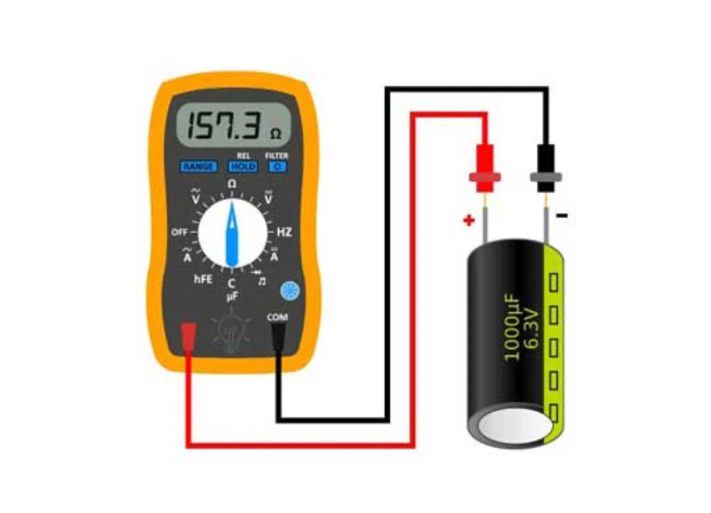
- Capacitance Testing: Use a digital multimeter (DMM) with a capacitance measurement function. Connect the multimeter leads to the MLCC’s external electrodes. The multimeter will display the actual capacitance value, which should be within the tolerance range specified on the datasheet. If the value is outside the tolerance, the MLCC is defective.
- ESR Testing: Use an ESR meter or a LCR meter to measure the equivalent series resistance of the MLCC. ESR is measured at a specific frequency (typically 100kHz). Compare the measured ESR to the datasheet’s maximum ESR value. High ESR indicates a defective or degraded MLCC.
- Voltage Breakdown Testing: This test determines the maximum voltage the MLCC can withstand before breakdown. Use a high-voltage power supply and a current meter. Gradually increase the voltage applied to the MLCC until current flows (breakdown). The breakdown voltage should be at least 1.5 times the rated voltage. If it is lower, the MLCC is defective.
- Temperature Stability Testing: Place the MLCC in a temperature chamber and measure its capacitance at different temperatures (e.g., -55°C, 25°C, +125°C). The capacitance should remain within the datasheet’s temperature coefficient range. Significant capacitance drift indicates a problem with the dielectric material.
- Leakage Current Testing: Apply the rated voltage to the MLCC and measure the leakage current using a microammeter. The leakage current should be very low (typically less than 1μA). High leakage current indicates a defective dielectric or electrode.
For production testing, automated test equipment (ATE) is used to test multiple MLCCs simultaneously, ensuring consistency and efficiency. For lab testing, a basic DMM and ESR meter are sufficient for most applications.
What are the Failure Modes of MLCC Capacitors?
Understanding the failure modes of MLCC capacitors helps you diagnose problems in your circuits and take steps to prevent failures. Below are the most common failure modes, their causes, and symptoms.
- Dielectric Breakdown: This is the most common failure mode. It occurs when the MLCC is subjected to a voltage higher than its rated voltage, causing the dielectric material to break down and conduct current. Symptoms include short circuits, overheating, and damage to other components. Causes include overvoltage, voltage spikes, and incorrect voltage rating selection.
- Cracking: MLCCs are brittle and can crack if subjected to excessive mechanical stress. Cracks can occur during soldering (thermal stress), handling, or vibration. Symptoms include intermittent connections, increased ESR, and capacitance loss. Causes include improper soldering temperature, mechanical impact, and vibration in automotive or industrial applications.
- ESR Increase: Over time, the ESR of an MLCC can increase due to aging, humidity, or contamination. This leads to increased power loss, overheating, and reduced circuit efficiency. Symptoms include higher operating temperatures, voltage ripple, and reduced performance in high-frequency applications. Causes include prolonged exposure to high temperatures, humidity, and chemical contamination.
- Capacitance Drift: Class II and Class III MLCCs can experience capacitance drift due to temperature changes, voltage changes, or aging. This can affect circuit performance, especially in precision applications. Symptoms include incorrect timing, signal distortion, and reduced filter efficiency. Causes include temperature extremes, overvoltage, and long-term use.
- Electrode Migration: This occurs when metal ions from the electrodes migrate through the dielectric material, causing short circuits. It is more common in high-humidity environments. Symptoms include short circuits and sudden failure. Causes include high humidity, high voltage, and poor dielectric quality.
MLCC VS Tantalum Capacitors: Which is Better?
MLCC and tantalum capacitors are both popular choices for surface mount applications, but they have distinct characteristics that make them suitable for different use cases. Below is a detailed comparison table to help you decide which is better for your project.
| Characteristic | MLCC Capacitor | Tantalum Capacitor |
|---|---|---|
| Capacitance Density | High (up to 1000μF for large sizes) | Very high (up to 10,000μF for small sizes) |
| ESR | Low (typically 1–100mΩ) | Low to medium (typically 10–500mΩ) |
| Voltage Rating | Wide (4V–1000V) | Limited (2V–50V) |
| Temperature Range | Wide (-55°C to +150°C) | Moderate (-55°C to +125°C) |
| Reliability | High (no electrolyte leakage) | High (but can fail due to voltage spikes) |
| Cost | Low to moderate | Moderate to high |
| Size | Very small (01005 to 2225) | Small to medium (larger than MLCC for same capacitance) |
| Failure Modes | Dielectric breakdown, cracking, ESR increase | Short circuits (due to voltage spikes), leakage |
| Best Applications | High-frequency circuits, compact devices, high-voltage applications | High-capacitance applications, low-voltage devices, medical equipment |
In general, MLCCs are better for high-frequency, high-voltage, and compact applications, while tantalum capacitors are better for high-capacitance, low-voltage applications where space is less of a concern. For many applications, a combination of both may be used to balance performance and cost.
What is the Difference between Polymer Capacitor and MLCC?
Polymer capacitors (also known as polymer electrolytic capacitors) and MLCCs are both used in modern electronics, but they differ in construction, performance, and applications. Below is a comparison table to highlight the key differences.
| Characteristic | MLCC Capacitor | Polymer Capacitor |
|---|---|---|
| Construction | Layered ceramic dielectric and metal electrodes | Polymer electrolyte, anode, and cathode |
| Capacitance Density | High (up to 1000μF) | Very high (up to 100,000μF) |
| ESR | Low (1–100mΩ) | Very low (0.1–10mΩ) |
| Voltage Rating | Wide (4V–1000V) | Limited (2V–63V) |
| Temperature Range | Wide (-55°C to +150°C) | Moderate (-40°C to +105°C) |
| Reliability | High (no electrolyte leakage) | High (low leakage, long lifespan) |
| Size | Very small (01005 to 2225) | Medium to large (larger than MLCC for same capacitance) |
| Noise | May generate piezoelectric noise | No piezoelectric noise |
| Best Applications | High-frequency circuits, compact devices, high-voltage applications | Power supplies, voltage regulation, noise filtering in low-voltage devices |
What is the Difference between MLCC and SLCC?
MLCC (Multilayer Ceramic Capacitor) and SLCC (Single-Layer Ceramic Capacitor) are both ceramic capacitors, but they differ in structure, performance, and applications. Below is a clear comparison table to help you understand the differences.
| Characteristic | MLCC Capacitor | SLCC |
|---|---|---|
| Structure | Multiple layers of ceramic dielectric and internal electrodes stacked alternately | Single layer of ceramic dielectric with electrodes on both sides |
| Capacitance | High (1pF–1000μF) due to multiple layers in parallel | Low (1pF–1000pF) due to single layer |
| Size | Compact (01005 to 2225) with high capacitance density | Small to medium, but lower capacitance density than MLCC |
| Dielectric Material | Class I (C0G), Class II (X7R), Class III (Y5V) ceramics | High-frequency ceramics (e.g., alumina) for stable performance |
| Electrode Material | Internal: nickel/copper; External: copper/nickel/tin | Platinum, gold, or titanium-tungsten (for金丝键合) |
| High-Frequency Performance | Good, but limited by internal electrode inductance | Excellent, with low parasitic inductance/resistance |
| Applications | Consumer electronics, automotive, industrial, power supplies | RF circuits, microwave equipment, radar, microelectronic devices |
| Cost | Low to moderate, suitable for high-volume production | High, due to贵金属 electrodes and precision manufacturing |
How Much Do MLCC Capacitors Cost?
The cost of MLCC capacitors varies widely depending on factors like size, capacitance, voltage rating, dielectric material, and quantity. Below is a breakdown of typical costs for common MLCC configurations, based on volume purchases (1000+ units), to help you budget for your project.
Small Size MLCCs (01005, 0201, 0402): These are the most affordable MLCCs, with prices ranging from $0.003 to $0.05 per unit. For example, a 0402 MLCC with 100nF capacitance and 25V rating costs approximately $0.005 per unit in volume.
Medium Size MLCCs (0603, 0805): Prices range from $0.008 to $0.10 per unit. A 0603 MLCC with 1μF capacitance and 50V rating costs around $0.015 per unit in volume.
Large Size MLCCs (1206, 2225): These are more expensive due to their larger size and higher capacitance. Prices range from $0.05 to $0.50 per unit. A 1206 MLCC with 10μF capacitance and 100V rating costs approximately $0.08 per unit in volume.
High-Voltage MLCCs (100V+): High-voltage MLCCs (200V and above) are more expensive due to the thicker dielectric layers required. Prices range from $0.10 to $2.00 per unit, depending on capacitance and voltage.
Specialty MLCCs: Automotive-grade (AEC-Q200), industrial-grade, and high-reliability MLCCs cost more than standard MLCCs. Prices range from $0.05 to $5.00 per unit, depending on the specifications.
Quantity also plays a significant role in cost. Purchasing MLCCs in large volumes (10,000+ units) can reduce the per-unit cost by 30–50%. Additionally, brand name MLCCs (like Murata, Samsung, TDK) are slightly more expensive than generic brands but offer better quality and reliability.
FAQs About MLCC Multilayer Ceramic Capacitor
Q1: Are MLCC and Electrolytic Capacitors Equivalent?
A1: No, MLCC and electrolytic capacitors are not equivalent. MLCCs use ceramic dielectric and have small size, low ESR, and excellent high-frequency performance. Electrolytic capacitors use liquid or solid electrolyte, have high capacitance values, but larger size and higher ESR. They are used for different applications: MLCCs for high-frequency filtering and compact devices, electrolytic for high-capacitance applications like power supplies. You cannot directly replace one with the other without adjusting the circuit design.
Q2: Does a MLCC Capacitor Make Noise When it Goes Bad?
A2: Yes, an MLCC capacitor can make noise when it goes bad, but it is not common. The noise is typically a faint buzzing or clicking sound caused by piezoelectric effect, where the ceramic material expands and contracts due to AC voltage. This noise is more likely to occur if the MLCC is cracked, has high ESR, or is operating at high voltage. A noisy MLCC is a sign of degradation and should be replaced to prevent failure.
Q3: What is MLCC capacitor ESR?
A3: MLCC capacitor ESR (Equivalent Series Resistance) is the total resistance of the capacitor’s electrodes and dielectric, measured in milliohms. It represents the power loss of the MLCC at high frequencies. Low ESR is critical for high-frequency applications, as it reduces power loss and improves efficiency. Typical ESR values for MLCCs range from 1mΩ to 100mΩ, depending on size, capacitance, and frequency. You can find the ESR value in the MLCC’s datasheet.
Q4: Who are the top MLCC capacitor manufacturers?
A4: The top MLCC capacitor manufacturers are Murata (Japan), Samsung Electro-Mechanics (South Korea), TDK (Japan), Yageo (Taiwan), and Fenghua Advanced Technology (China). These manufacturers produce high-quality MLCCs for consumer, automotive, industrial, and military applications. Murata is the market leader, known for its high-reliability and high-performance MLCCs, while Samsung and TDK focus on consumer electronics and automotive-grade MLCCs. Yageo and Fenghua Advanced Technology offer cost-effective options for high-volume production.
Q5: What is the difference between MLCC vs electrolytic capacitor?
A5: The key differences between MLCC and electrolytic capacitors are construction, performance, and applications. MLCCs have ceramic dielectric and layered electrodes, small size, low ESR, and high-frequency performance. Electrolytic capacitors have liquid/solid electrolyte, large size, high capacitance, and higher ESR. MLCCs are used for high-frequency filtering and compact devices, while electrolytic capacitors are used for high-capacitance applications like power supplies and voltage regulation.
Q6: Can MLCC capacitors be used in high-temperature applications?
A6: Yes, most MLCC capacitors can be used in high-temperature applications. Standard MLCCs operate between -55°C and +125°C, while industrial and automotive-grade MLCCs can withstand temperatures up to +150°C. Choose MLCCs with a wide temperature range (e.g., X7R, X8R dielectric) for high-temperature applications like automotive underhood systems or industrial furnaces. Always check the datasheet for the exact operating temperature range.
Q7: How long do MLCC capacitors last?
A7: MLCC capacitors have a long lifespan, typically 20,000 to 100,000 hours of operation at room temperature. Their lifespan is affected by temperature, voltage, and humidity. Operating an MLCC at high temperatures (above +85°C) or high voltage (close to its rated voltage) will reduce its lifespan. Unlike electrolytic capacitors, MLCCs do not dry out or leak, so they can last the lifetime of the device if used correctly.
Q8: Can MLCC capacitors be soldered with reflow soldering?
A8: Yes, MLCC capacitors are designed for reflow soldering, which is the standard method for surface mount assembly. Most MLCCs can withstand reflow temperatures up to 260°C for 10–30 seconds, as specified in the datasheet. To prevent damage, follow the recommended reflow profile, avoid excessive heat, and ensure proper alignment of the MLCC on the circuit board. Cracking can occur if the reflow temperature is too high or the cooling rate is too fast.