 language
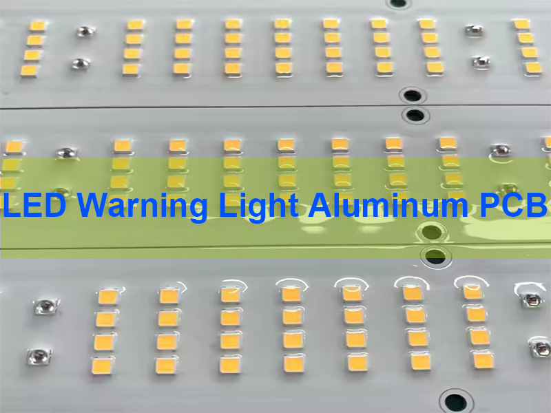
LED Warning Light Aluminum PCB – High Thermal for Construction Sites
LED Warning Light Aluminum PCB is a metal-core printed circuit board specifically engineered to deliver efficient heat dissipation and stable electrical performance for high-brightness warning light systems in harsh environments. This article explains how optimized thermal design, material selection, and manufacturing processes improve reliability, brightness consistency, and long-term performance in construction site applications.
Best Technology is a professional manufacturer specializing in LED Warning Light Aluminum PCB with 20 years of experience in high-reliability PCB and PCBA solutions. We understand that harsh construction environments demand boards with strong dust resistance, vibration tolerance, and stable thermal performance, which is why our aluminum PCB solutions are engineered with optimized heat paths and robust structural design. For applications requiring high visibility, we focus on thermal efficiency and current balance to ensure consistent brightness and signal clarity.
In large-volume deployments, we support customers with scalable production capacity, stable supply chains, and high-yield manufacturing processes, ensuring reliable delivery without compromising quality. For extreme environments, we integrate advanced materials and proven thermal structures to maintain performance under high dust and vibration conditions, making our circuit board and assembly solutions highly dependable for real-world field use. For reliable and high-performance LED Warning Light Aluminum PCB solutions, pls feel free to contact us at +84-827-237566.
What Is LED Warning Light Aluminum PCB and How Does It Work?
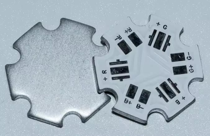
LED Warning Light Aluminum PCB uses a metal core structure to dissipate heat efficiently from high-power LEDs. It replaces traditional FR4 substrates in high-thermal applications.
Structure includes:
- Copper circuit layer
- Thermal dielectric layer
- Aluminum base
The aluminum base acts as a heat sink, transferring thermal energy away from LEDs quickly.
In real-world applications, this structure significantly improves thermal management compared to standard PCBs.
Why Choose Our LED Warning Light Aluminum PCB Services?
Quality assurance, stable delivery, and engineering-driven design are essential for industrial LED applications. At Best Technology, our approach integrates design optimization and manufacturing control.
Quality control:
- 100% AOI + X-ray inspection
- Thermal simulation validation
- IPC Class 2 / Class 3 compliance
Lead time stability:
- Fast prototyping within 1.5 weeks
- MES traceability system
Engineering support:
- Free DFM optimization
- Thermal layout guidance
- LED current balancing design
Supply chain reliability:
- Verified LED and driver sourcing
- Full BOM management
In practice, combining process control with design optimization significantly improves yield and reduces field failure rates.
What Services and Certifications Ensure Reliable Aluminum PCB Manufacturing?
Reliable production requires certified systems and standardized processes. Below is a structured overview of our capabilities.
| Category | Details |
|---|---|
| Manufacturing Services | PCB fabrication, SMT assembly, thermal design support, box-build integration |
| Certifications | ISO9001, ISO13485, IATF16949, AS9100D |
| Inspection | AOI, SPI, X-ray, functional testing |
| Traceability | 5-second MES tracking system |
As a result, certified processes ensure consistency, traceability, and compliance across all production stages.
What Are the Key Pain Points in LED Warning Light Aluminum PCB Projects and How to Solve Them?
Most failures in LED warning systems originate from thermal imbalance and process instability. These issues directly impact brightness and lifespan.
Common challenges:
- Uneven heat distribution causing LED degradation
- Solder voids under high-power LEDs
- Thermal interface resistance too high
- Inconsistent brightness across boards
- Low assembly yield in mass production
Our solutions:
- Optimized copper layout for heat spreading
- Vacuum reflow to reduce void rate
- High thermal conductivity dielectric materials
- Strict current balancing design
- Process standardization for stable yield
Overall, addressing thermal and process variables early ensures long-term reliability and consistent optical performance.
Why Is Thermal Management Critical for Warning Light LED PCBs?
Heat directly affects LED efficiency and lifespan. Excessive junction temperature leads to brightness decay and early failure.
Key impacts:
- Lumen degradation
- Color shift
- Shortened lifespan
Efficient heat dissipation ensures stable performance under continuous operation.
From an engineering perspective, thermal design is the primary factor influencing LED reliability and system durability.
How Do Aluminum PCBs Compare to FR4 in Construction Site Lighting?
Aluminum substrates offer superior mechanical strength and thermal performance compared to traditional FR4. In construction sites where equipment is subjected to drops, shocks, and intense UV exposure, the durability of the PCB Aluminum Warning Light LED is a significant advantage.
| Feature | Aluminum PCB | Standard FR4 PCB |
|---|---|---|
| Thermal Conductivity | 1.0 – 3.0 W/m.K | ~0.25 W/m.K |
| Mechanical Stability | High (Resists warping) | Moderate (Flexible) |
| Thermal Expansion | Matched to Aluminum housings | High CTE (Risk of stress) |
| Durability | Excellent for outdoors | Prone to UV degradation |
Therefore, while FR4 might be suitable for low-power indoor electronics, it cannot match the ruggedness required for a high-intensity Light Warning LED Aluminum PCB.
How Is LED Warning Light Aluminum PCB Manufactured Step by Step?
The manufacturing of LED Warning Light Aluminum PCB is a tightly controlled process where each step directly affects thermal performance, electrical stability, and long-term reliability. For construction-site warning lights, the focus is on heat dissipation, structural durability, and consistent assembly quality.
Film Set Verification
This step confirms that production data matches the released design, including copper layout and pad geometry. Any mismatch can disrupt current distribution and thermal paths, leading to brightness inconsistency or overheating.
Material Cutting
The aluminum substrate is cut into panels with controlled dimensions. Stable panel size ensures accurate alignment in later processes and prevents positioning deviations that affect LED placement and heat flow.
Surface Grinding
Grinding removes oxidation and contaminants, improving copper adhesion. A uniform surface ensures stable conductivity and reduces the risk of delamination under thermal cycling.
Circuit Imaging
The copper pattern is transferred onto the board, defining both electrical routing and thermal spreading areas. For LED warning lights, this step determines how effectively heat is distributed across the board.
Circuit QC
Inspection verifies trace width and spacing. Since resistance follows R = ρL / A, reduced copper area increases resistance and heat generation, directly impacting LED efficiency.
Etching
Unwanted copper is removed to form the final circuit. Poor control may narrow traces or create uneven edges, leading to current crowding and localized thermal buildup.
Etching QC
This step ensures the etched copper matches design intent. It confirms that thermal copper areas are intact and capable of supporting required heat dissipation.
CCD Target Alignment
CCD alignment ensures precise positioning for solder mask and downstream processes. Accurate targeting prevents pad misalignment that could affect solder quality and thermal transfer.
Secondary Grinding
A second surface treatment improves coating adhesion and process consistency. This enhances resistance to dust and vibration in harsh environments.
Solder Mask Application
Solder mask protects the circuit and defines exposed pads. Proper mask opening ensures good solder wetting, which is critical for both electrical connection and heat conduction.
Solder Mask QC
Inspection checks alignment and adhesion. Poor mask quality can reduce effective pad area, increasing thermal resistance at the solder interface.
Silkscreen (Legend Printing)
Markings provide polarity and identification. This reduces assembly errors and supports traceability in production and field maintenance.
Board Baking
Baking removes moisture and stabilizes the board. Moisture control improves solderability and prevents defects during assembly.
Surface Finish (Lead-Free HASL)
Surface finishing ensures reliable solder joints. A uniform finish supports consistent thermal contact between LED and PCB.
Routing / Profiling
The board is shaped to final dimensions. Accurate profiling ensures proper fit within warning light housings and avoids mechanical stress.
Electrical Testing
Testing verifies continuity and insulation. This ensures stable current flow before assembly, preventing early-stage failures.
FQC (Final Quality Control)
Final inspection checks appearance, dimensions, and workmanship. It ensures the board meets production standards before release.
FQA (Final Quality Assurance)
Quality assurance confirms compliance with all process and inspection requirements, ensuring batch consistency.
Packaging
Proper packaging protects against moisture, oxidation, and mechanical damage during transport and storage.
Process Issue Recording
All production issues are recorded for analysis and continuous improvement. This enables process optimization and stable quality across batches.
Notably, this step-by-step manufacturing flow ensures that LED Warning Light Aluminum PCB achieves consistent thermal performance, high assembly yield, and reliable operation in demanding construction environments.
What Design Considerations Improve LED Warning Light PCB Performance?
The performance of a LED Warning Light Aluminum PCB is fundamentally determined by how effectively heat is managed and how uniformly electrical current is distributed. Poor layout decisions often lead to thermal hotspots, brightness inconsistency, and premature LED degradation. A well-engineered design integrates thermal calculations, electrical balancing, and manufacturability from the beginning.
Thermal path design and junction temperature control
The primary objective is to control the LED junction temperature (Tj), as it directly affects lumen output and lifetime. The simplified thermal model is:
Tj = Ta + (Rth_total × Pd)
- Tj: LED junction temperature
- Ta: Ambient temperature
- Rth_total: Total thermal resistance (junction → ambient)
- Pd: Power dissipation per LED
To improve performance, designers must minimize Rth_total, which includes:
- Junction-to-case resistance (LED package)
- Case-to-board interface (solder + pad design)
- Board thermal resistance (dielectric + aluminum base)
For example, reducing thermal resistance from 10°C/W to 5°C/W at 1W power lowers junction temperature by 5°C, which can extend LED lifetime by more than 20% in practical applications.
Wide copper traces and thermal spreading design
Copper acts as a lateral heat spreader before heat transfers into the aluminum base. Increasing copper width and thickness reduces thermal resistance.
Thermal resistance approximation for copper spreading:
Rth ≈ L / (k × A)
- L: Heat flow length
- k: Thermal conductivity of copper (~400 W/m·K)
- A: Cross-sectional area
Design recommendations:
- Use 1oz–3oz copper for high-power LEDs
- Maximize copper area under LED pads
- Avoid narrow traces near heat sources
This reduces localized heat concentration and improves uniform temperature distribution across the board.
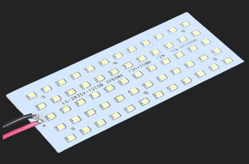
Uniform LED spacing and current balancing
Uneven LED placement leads to thermal coupling, where adjacent LEDs raise each other’s temperature. This creates brightness inconsistency and accelerates aging.
Spacing guidelines:
- Maintain consistent pitch between LEDs
- Avoid clustering high-power LEDs in small areas
- Use symmetric layout for multi-channel designs
From an electrical perspective, LED current must be balanced. For parallel LED strings:
I_total = I1 + I2 + … + In
If resistance varies between paths, current imbalance occurs, causing some LEDs to overheat. Adding current-limiting resistors or using constant current drivers helps stabilize performance.
Minimizing thermal resistance path
The vertical heat transfer path is critical in aluminum PCBs. The dielectric layer is the weakest point due to its lower thermal conductivity.
Typical dielectric conductivity:
- Standard: 1.0–2.0 W/m·K
- High-performance: 3.0–8.0 W/m·K
Thermal resistance across dielectric:
Rth_dielectric = t / (k × A)
- t: Thickness of dielectric layer
- k: Thermal conductivity
- A: Heat transfer area
Design optimization:
- Reduce dielectric thickness (within insulation limits)
- Increase pad area under LEDs
- Select high thermal conductivity materials
This directly lowers the thermal barrier between LED and aluminum base.
Via design for hybrid structures
In hybrid designs (e.g., FR4 + aluminum), thermal vias are used to transfer heat efficiently.
Key via design rules:
- Use multiple small vias instead of one large via
- Via diameter: 0.2–0.4 mm typical
- Fill or tent vias to improve thermal conduction
Effective thermal conductivity increases with via density, improving vertical heat transfer.
Surface finish and solder joint reliability
Solder joints act as both electrical and thermal interfaces. Voids or poor wetting increase thermal resistance.
Recommended practices:
- Use optimized stencil design to reduce voids
- Control reflow profile for uniform soldering
- Prefer ENIG or OSP for stable LED mounting
Lower void rate directly improves thermal conduction and mechanical reliability.
Design for manufacturability (DFM) considerations
Even a thermally optimized design can fail if it cannot be manufactured consistently.
- Avoid overly tight spacing that affects SMT placement
- Ensure pad design matches LED package footprint
- Maintain consistent copper distribution to avoid warpage
Good DFM ensures high yield and repeatable performance in mass production.
From an engineering perspective, integrating thermal modeling, electrical balance, and manufacturability into the PCB layout is the most effective way to improve LED warning light reliability and long-term stability.
Which Industries Use Aluminum PCB LED Warning Light Solutions?
The demand for LED Warning Light Aluminum PCB technology spans multiple high-stakes sectors. Each industry has unique requirements, but all converge on the need for zero-failure performance under stress.
Construction & Mining
- Heavy machinery and site perimeters use these PCBs for high-visibility beacons that must operate 24/7 in dusty, high-vibration environments.
Emergency Services & Law Enforcement
- Lightbars on police cruisers and ambulances require Aluminum PCB LED Warning Light modules that can handle rapid flashing patterns without overheating.
Marine & Off-Shore
- Warning lights on docks and buoys utilize the corrosion resistance of treated aluminum PCBs to withstand salt spray and humidity.
Aerospace Ground Support
- Airport tarmac vehicles use Warning Light Aluminum PCB LED systems to ensure visibility to pilots, requiring high-reliability components that meet aviation safety grades.
In short, these diverse industries rely on the thermal stability of aluminum substrates to maintain safety and operational continuity in hazardous zones.
How to Ensure High Assembly Yield in LED Aluminum PCB Production?
High yield depends on process control and material quality.
- Stencil optimization
- Controlled reflow profile
- Void reduction techniques
- Inline inspection systems
Consequently, stable processes reduce defects and ensure consistent product quality.
Looking for High-Reliability LED Warning Light Aluminum PCB for Harsh Environments?
If your application demands stable brightness, long lifetime, and strong heat dissipation, LED Warning Light Aluminum PCB is the foundation. In construction sites, traffic control, and industrial safety systems, overheating is the main cause of LED failure.
Core parameters to focus on:
- Thermal conductivity: 1.0–3.0 W/m·K (standard), up to 8 W/m·K (high-end)
- Dielectric thickness: 75–150μm
- Copper thickness: 1oz–3oz
- Operating temperature: -40°C to 150°C
- LED lifespan: 50,000–100,000 hours
Why Partner With Us for Your LED Warning Light Aluminum PCB Needs?
We combine rapid prototyping with mass-production stability. Our Aluminum PCB LED Warning Light solutions focus on four pillars:
Quality (100% E-test and AOI inspection), Lead Time (Quick-turn prototypes in 24-48 hours), Cost-Efficiency (Optimized material sourcing), and Supply Chain Resilience (Direct manufacturer transparency).
Overall, choosing the right PCB partner ensures that your construction site safety equipment maintains peak performance regardless of ambient temperature or operational duration.
We provide LED Warning Light Aluminum PCB solutions with full engineering support and fast delivery. If you have any requirements, please contact Best Technology at sales@vn.danyupcbs.com
FAQs About LED Warning Light Aluminum PCB
What is the typical thermal conductivity for a Warning Light Aluminum PCB LED?
Most Warning Light Aluminum PCB LED applications use a conductivity of 1.5W/m.K to 2.0W/m.K. This provides an optimal balance between cost and thermal performance for construction site beacons. For extreme high-power stadium or heavy-duty strobe lights, we offer up to 3.0W/m.K dielectric layers.
Why should I use Aluminum instead of Copper-core PCBs for warning lights?
While copper-core PCBs have better thermal conductivity, an Aluminum PCB LED Warning Light is significantly lighter and more cost-effective. For construction site equipment, the weight reduction and lower material cost of aluminum make it the industry standard without sacrificing necessary cooling performance.
How does moisture affect the LED Light Warning Aluminum PCB in outdoor use?
Moisture can lead to electrochemical migration if the LED Light Warning Aluminum PCB is not properly protected. We recommend a conformal coating (silicone or acrylic) after assembly to seal the components and traces from humidity, ensuring the aluminum base remains isolated and corrosion-free.
What thickness is best for Aluminum PCB LED warning lights?
Typical aluminum base thickness ranges from 1.0mm to 2.0mm depending on thermal requirements and mechanical strength.
What surface finish is suitable for LED Aluminum PCB?
OSP and HASL are commonly used, while ENIG is preferred for higher reliability applications.
How to ensure uniform brightness in LED warning PCB?
Ensure balanced current distribution, consistent LED placement, and stable power supply design.
How long does LED aluminum PCB last?
With proper design and thermal management, lifespan can exceed 50,000 hours.
What is the maximum operating temperature for these PCBs?
Our PCB Aluminum Warning Light LED products are designed to operate reliably at ambient temperatures up to 85°C, with the board itself capable of handling internal temperatures up to 130°C. This ensures stability even when the warning light is exposed to direct sunlight in desert environments.