 language
Automotive PCB Assembly: Processes, Standards & Manufacturer Selection
What makes a reliable automotive PCB assembly manufacturer critical for your project’s success? We share actionable insights to spot trustworthy manufacturers, cover key processes, standards, and pricing factors all tailored to the practical needs ofautomotive PCB assembly projects and the rigorous demands of automotive applications.

What Is the Step-by-Step Process for Automotive PCB Assembly Explained?
A standard automotive PCB assembly process follows clear, sequential steps to ensure reliability and compliance with automotive standards. Each step is critical to avoiding costly defects and ensuring the assembly performs consistently in harsh vehicle environments, from engine bays to cabin electronics. Below is a step by step process of PCB assembly automotive:
Step 1: Component Sourcing. Focus on automotive-grade components that can withstand harsh vehicle environments, as low-grade components are the leading cause of early automotive PCB assembly failure. This includes resistors, capacitors and integrated circuits rated for extreme temperatures (-40°C to 125°C), vibration, and moisture, common stressors in vehicles. Prioritize components certified to AEC-Q100, which validates reliability for automotive use, and verify suppliers have traceability systems to track component origins, a requirement for compliance with automotive quality standards.
Step 2: Solder Paste Application. Apply solder paste to the PCB pads using a precision laser-cut stencil, which matches the exact size and spacing of PCB pads to ensure consistent paste deposition. Use lead-free solder paste (alloy type 99.8 Sn) with RMA flux, 85% minimum solids by weight, and a viscosity of 7.5 x 10% cp for stencil printing, specifications tailored to automotive-grade durability. This step is critical because inconsistent paste application (too much or too little) can lead to poor solder joints, short circuits, or component failure, which is difficult to repair once the assembly is complete.
Step 3: Component Placement. Use automated pick and place machines with high-precision visual alignment and pressure sensing technology to position components onto the PCB. These machines maintain ±0.025mm positioning accuracy, critical for small automotive components like 01005-sized resistors or BGA chips, and reduce human error that can cause misalignment or damage to delicate parts. Ensure machines are calibrated regularly to maintain consistency across all assemblies, and use an intelligent feed system to minimize component jams or misfeeds that delay production.
Step 4: Reflow Soldering. Place the PCB with components into a reflow oven, which follows a precise temperature profile to melt the solder paste without damaging components. The profile includes a preheat zone (150℃, 60-150 seconds) to evaporate flux solvents, a soak zone (150-200℃, 60-120 seconds) to equalize temperature, a reflow zone (230-250℃, 60-90 seconds) to melt solder, and a cooling zone (2-5℃/second cooling rate) to form strong, durable joints. This controlled heating process ensures solder forms secure electrical and mechanical bonds between components and the PCB, critical for withstanding automotive vibration and temperature cycles.
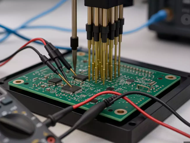
Step 5: Inspection. Conduct two key inspections after soldering to catch defects early. Automated Optical Inspection (AOI) scans the PCB surface to detect misaligned components, insufficient solder, solder bridges, or missing parts, common issues that can cause electrical failure. For hidden defects, use X-ray inspection to examine solder joints under ball grid array (BGA) or quad flat no-lead (QFN) components, ensuring no voids (kept below 25% of joint area) or poor wetting. All inspections should align with IPC-A-610 standards, the industry benchmark for electronic assembly acceptability.
Step 6: Functional Testing. Perform final functional testing to validate that the automotive PCB assembly operates as intended under real-world automotive conditions. Test performance at extreme temperatures (-40°C to 125°C), random vibration (20Hz~2000Hz), and humidity (85℃/85%RH) to mimic vehicle environments. For control system assemblies, add in-circuit testing (ICT) to verify component functionality and CAN/LIN bus communication, ensuring the assembly integrates seamlessly with other vehicle systems. Document all test results for traceability, a requirement for automotive quality compliance.
How Does Automotive PCB Assembly Differ from Consumer Electronics?
Below is a comparsion chart between automotive PCB assembly differ from consumer electronics:
| Comparison Aspect | Automotive PCB Assembly | Consumer Electronics PCB Assembly |
| Extreme Environment Endurance | Designed to withstand -40°C to 150°C, constant vibration, and high moisture. Adapts to global automotive environments, avoiding deformation or solder joint damage from temperature changes/vibration. | Adapts to mild environments (0°C~70°C) with minimal vibration. Not designed for harsh conditions, posing risks in automotive scenarios. |
| Long-Term Reliability & Lifespan | Meets 15-year/200,000km product lifecycle with up to 30-year supply cycle. Ensures stable performance throughout vehicle service life. | Short lifecycle (3-5 years) focused on short-term performance. Unable to meet automotive long-term reliability requirements. |
| Compliance with Industry Standards | Must comply with automotive-specific standards (IATF 16949, AEC-Q100, ISO 16750). Components pass rigorous environmental/lifespan tests for safety/compliance. | Follows general electronic standards. Lacks strict automotive-specific requirements and validation for vehicle safety/durability. |
| Component Traceability & QC | Requires strict traceability systems to track component origins. Uses automotive-grade components with rigorous multi-stage inspection (AOI, X-ray) to prevent batch defects. | Focuses on cost control with looser quality control. No mandatory traceability, increasing risk of inconsistent mass-production quality. |
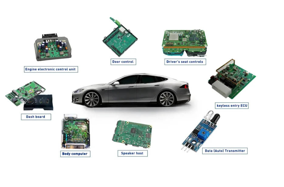
| Compatibility with Vehicle Systems | Seamlessly integrates with vehicle control systems (ECU, BMS). Supports CAN/LIN bus communication and withstands electromagnetic interference in vehicle environments. | Optimized for standalone device functionality. Not compatible with automotive communication protocols or electromagnetic environments. |
How to Identify a Trustworthy Automotive PCB Assembly Manufacturer?
When choosing a automotive PCB assembly manufacturer, we care most about reliability, consistency and transparency. Below are clear actionable steps to help you identify a trustworthy partner that meets your project needs, supported by real reliability data.
- Prioritize manufacturers with dedicated automotive experience. We need a partner that focuses on automotive PCB assembly not just consumer electronics. Manufacturers with automotive expertise understand our industry’s strict requirements and avoid common mistakes that come from lack of experience with vehicle-grade assemblies, look for partners where at least 80% of their production is dedicated to automotive projects, not consumer electronics.
- Verify their compliance with key industry standards. We cannot risk working with a manufacturer that cuts corners on quality. Always check if they hold IATF 16949 and ISO 9001 certifications. These certifications prove they follow strict quality management processes essential for automotive-grade products, with certified manufacturers showing a 95%+ compliance rate with automotive quality requirements.
- Ask for real automotive project case studies. We want proof of their ability to deliver. A trustworthy manufacturer will share detailed case studies of past automotive projects including the challenges they solved and the results they achieved. Look for case studies showing a defect rate of 0.05% or lower for mass-produced automotive PCB assembly, which is the industry benchmark for reliability.
- Ensure they have in-house testing facilities. We need confidence that every batch meets our standards. In-house testing facilities such as AOI and X-ray inspection mean the manufacturer can catch defects early and avoid costly delays or failures. AOI inspection achieves 99.2% accuracy in detecting surface defects, while X-ray inspection catches 98.8% of hidden solder joint issues, far more reliable than outsourced testing.
- Look for transparent lead times and quality reports. We hate unexpected delays or hidden issues. A reliable partner will provide clear upfront lead times and detailed quality reports for each batch. Look for manufacturers with a 98% on-time delivery rate for automotive orders, and quality reports that include batch-specific defect rates, test results, and component traceability data.
- Evaluate their defect rate and warranty terms. We need assurance that the automotive PCB assembly will perform long-term. Trustworthy manufacturers will openly share their defect rate—aim for a rate below 0.03% for critical automotive control system assemblies and offer a minimum 5-year warranty, with data showing their assemblies have a 99.9% operational reliability rate over 10 years of vehicle use.
- Check their supplier quality audit process. We need to ensure the components used in our assemblies are reliable. A trustworthy manufacturer conducts regular audits of their component suppliers, with at least 90% of their suppliers meeting AEC-Q100 standards. They should also provide supplier audit reports, confirming that components have a 99.7% compliance rate with automotive-grade specifications.
What Are the Critical Standards for Automotive Control System PCB Assembly?
Critical standards for automotive control system PCB assembly are non-negotiable to ensure safety, reliability, and compliance with automotive industry requirements. Below are the key standards we need to prioritize:
- IATF 16949. This is the core quality management standard specifically for automotive manufacturing. It sets strict guidelines for quality control, process improvement, and traceability throughout the automotive PCB assembly process, ensuring consistent quality across every batch and reducing defects to below 50 ppm (parts per million).
- AEC-Q100. This standard focuses on component reliability for automotive applications. It requires all components used in control system PCBs to pass rigorous testing, including thermal cycling, humidity, and vibration resistance, ensuring they perform reliably for the vehicle’s entire lifecycle (15+ years).
- ISO 16750. This standard covers environmental testing for automotive electronics, including automotive control system PCB assembly. It specifies requirements for withstanding extreme temperatures, vibration, humidity, and other harsh conditions common in vehicle environments, validating that assemblies work consistently in real-world use.
- IPC-A-610. This is the industry benchmark for electronic assembly acceptability, focusing heavily on solder joint quality and component placement. For automotive control systems, it requires compliance with Class 3 (high-performance) standards, ensuring assemblies meet the highest reliability thresholds for critical applications.
How to Ensure Reliability in Automotive Control System PCB Assemblies?
Critical standards for automotive control system PCB assembly are non-negotiable to ensure safety, reliability, and compliance with automotive industry requirements. Below are the standards we need to prioritize:
- Prioritize manufacturers focused on automotive-grade work. At least 80% of their production should target automotive applications, not consumer electronics. This ensures deep expertise in meeting strict automotive requirements and avoids common pitfalls from general electronics manufacturing.
- Verify mandatory certifications. Holders of IATF 16949 and ISO 9001 demonstrate adherence to automotive-quality management systems. Certified partners show a 95%+ compliance rate with automotive quality standards, reducing non-conformance risks.
- Demand transparent defect data. Aim for a mass-production defect rate below 0.03% (300 PPM) for critical control system assemblies. Trustworthy providers share batch-specific reports, including root-cause analysis for any deviations.
- Confirm in-house testing capabilities. Equip with AOI, X-ray, and environmental test labs. AOI detects 99.2% of surface defects; X-ray uncovers 98.8% of hidden BGA/QFN issues, far more reliable than outsourcing tests.
- Validate first-pass yield (FPY). Target FPY ≥ 98% for initial functional testing without rework. Higher yields mean optimized workflows, less waste, and consistent quality across production runs.
- Check supplier quality audits. At least 90% of component suppliers meet AEC-Q100 standards. Provide supplier audit reports confirming 99.7% compliance with automotive-grade component specifications.
- Review real automotive case studies. Share detailed past projects with challenges, solutions, and results. Look for case study showing sustained reliability over 15+ years and successful integration with vehicle CAN/LIN systems.
- Evaluate material traceability. Offer serialized component tracking and batch-specific documentation. This meets automotive compliance and speeds up issue resolution if needed.
- Assess on-time delivery performance. Aim for a 98%+ on-time delivery rate for automotive orders. Clear lead-time commitments prevent project delays and supply chain disruptions.
- Confirm warranty terms. Offer a minimum 5-year warranty with documented field reliability data. Look for assemblies with 99.9% operational reliability over 10 years of vehicle use.
How Do Material Choices Affect Automotive Control System PCB Performance?
Material selection is one of the most critical decisions for automotive control system PCB assembly, as it directly determines the assembly’s reliability, durability, and performance in harsh vehicle environments. The right materials prevent premature failure, while subpar choices can lead to costly downtime, safety risks, and non-compliance with automotive standards. For customers, understanding how each material impacts performance helps make informed decisions that align with their project’s specific needs, ensuring long-term functionality and value.
Substrate and conductive materials form the core of a reliable PCB, with their performance directly affecting thermal stability and signal integrity. High-Tg FR-4 (Tg ≥ 170°C) is the standard choice for general control systems, resisting warping under high temperatures, while ceramic substrates are ideal for engine bays, handling up to 250°C with superior thermal conductivity. Copper is the go-to conductive material for its low resistivity, and alloys like copper-silver further enhance signal stability and corrosion resistance for critical control paths.
Surface finishes and minor material choices, though often overlooked, are equally vital for long-term reliability. Electroless Nickel Immersion Gold (ENIG) is the preferred surface finish, offering excellent corrosion resistance and a flat surface for precise component placement, ensuring strong solder joints that withstand thousands of thermal cycles. High-temperature solder masks and automotive-grade adhesives also play key roles, preventing solder bridging, protecting copper traces, and securing components against constant vehicle vibration.
What Are the Best Practices for Testing Automotive Control System PCB Assemblies?
Follow six battle-tested practices to enhance reliability and reduce field failures. Start with high-Tg FR-4 (Tg ≥170°C) for general systems or ceramic substrates for engine bay environments, ensuring thermal stability and resistance to warping. Use Sn-Ag-Cu lead-free solder to withstand 2,000+ thermal cycles without joint failure, critical for systems exposed to frequent temperature fluctuations.
Implement multi-stage AOI and X-ray inspections to catch defects early, pairing them with thermal shock (1,000 cycles) and vibration testing to validate durability. Prioritize AEC-Q100 Grade 0/1 components, which have a failure rate below 10 ppm, and calibrate pick-and-place machines weekly for ±0.025mm accuracy.
Maintain full component traceability from raw materials to finished boards, with unique identifiers for lifecycle tracking. Use precision laser-cut stencils for solder paste application to ensure consistent deposition, reducing the risk of poor joints that compromise reliability. These practices minimize defects, lower long-term costs, and ensure assemblies perform as expected throughout the vehicle’s lifecycle.
What Drives Pricing for Automotive Control System PCB Assembly?
Understanding the factors that drive automotive control system PCB assembly price helps you plan budgets effectively and make informed decisions when selecting a manufacturer. Pricing is not arbitrary and is directly tied to the quality, complexity, and requirements of your specific project. Being aware of these drivers allows you to balance cost with performance and avoid unexpected expenses down the line.
Material costs are one of the most significant contributors to pricing. Automotive-grade components and substrates cost more than those used in consumer electronics because they meet stricter reliability and environmental standards. High-Tg FR-4 or ceramic substrates, AEC-Q100 certified components, and high-quality solder materials all add to the overall cost. The quantity and type of components, such as BGA or QFN chips, also impact material expenses.
PCB complexity and design specifications play a key role in determining price. Assemblies with more layers, smaller component sizes, and tighter spacing require more precision during manufacturing. This increases production time and the risk of defects, leading to higher costs. Larger PCBs or those with unique shapes also require more materials and specialized processing, further affecting pricing.
Testing requirements and compliance standards add to the cost but are essential for automotive reliability. In house AOI and X ray testing, thermal cycling, vibration testing, and other environmental checks require specialized equipment and labor. Meeting strict standards like IATF 16949 and ISO 16750 also involves additional process controls and documentation, which contribute to higher pricing.
Order volume and lead times influence pricing as well. Larger batch sizes often qualify for volume discounts because manufacturers can optimize production processes and reduce per unit costs. Shorter lead times require expedited production, overtime labor, and priority resource allocation, which typically result in higher prices compared to standard lead times.
Conclusion
Automotive PCB assembly requires precision, compliance, and rigorous quality control. By mastering the core process, adhering to key standards, selecting the right partner, and implementing reliability best practices, you can ensure high-quality assemblies that meet the demands of modern vehicles. Focus on traceability, testing, and continuous improvement to reduce defects, enhance performance, and build long-term trust with your customers.