 language
Which is Positive and Negative in Capacitor Symbol?
Capacitors are common components on circuit boards, but not all capacitors have polarity. For those that do—especially electrolytic capacitors—knowing which side is positive (+) and which is negative (−) is critical for safe and correct operation.
This guide explains capacitor polarity symbols, diagrams, and how to identify positive and negative terminals, along with practical tips for checking polarity using a multimeter.
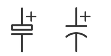
What Is the Positive and Negative Symbol on a Capacitor?
In circuit schematics, capacitor symbols help engineers identify component type and polarity. The symbol design often indicates whether the capacitor is polarized.
For non-polarized capacitors, the schematic symbol usually shows two parallel lines. These lines represent two plates separated by dielectric material. Neither side is positive or negative.
For polarized capacitors, the symbol changes slightly. One side becomes curved or marked with a plus sign.
Typical polarized capacitor symbol features include:
- Straight plate with “+” sign → positive terminal
- Curved plate → negative terminal
- Arrow marking (some schematics) → negative direction
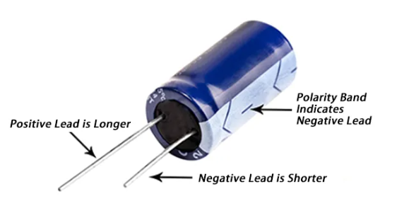
How to Tell Which Is Positive and Negative on a Capacitor?
In real components, capacitor polarity is indicated by physical markings. Manufacturers add stripes, symbols, or lead length differences. Several practical methods help identify polarity quickly.
1. Look for a polarity stripe
Electrolytic capacitors commonly include a vertical stripe. This stripe usually marks the negative terminal.
2. Check lead length
Through-hole electrolytic capacitors often use unequal leads.
- Long lead → Positive
- Short lead → Negative
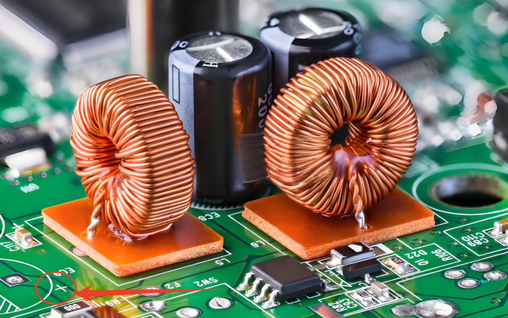
3. Observe PCB silk screen
Circuit boards usually include polarity indicators. The PCB marking may show:
- “+” sign for positive pad
- Shaded area for negative pad
4. Check the datasheet
Professional engineers always confirm polarity in the manufacturer datasheet. It ensures correct orientation before assembly.
In professional PCBA production environments, polarity verification is part of the assembly inspection process.
For example, manufacturers such as Best Technology integrate polarity verification in AOI inspection during SMT assembly. This step helps prevent reversed capacitor placement during production.
What Does the +/- on a Capacitor Mean?
The plus and minus symbols represent electrical polarity. They indicate how the capacitor should connect in a circuit.
The positive terminal connects to the higher voltage side of the circuit. The negative terminal connects to the lower potential or ground.
Polarized capacitors rely on internal chemical structures. These structures only function correctly when voltage flows in the correct direction.
If polarity remains correct, the capacitor provides stable capacitance and low leakage current. If polarity reverses, internal chemical reactions can occur. This condition may cause heating, leakage, or device failure.
Capacitor Positive Negative Diagram
A simple diagram helps visualize capacitor polarity, below are the common capacitor positive & negative diagram:
| Capacitor Type | Symbol Appearance | Polarity |
| Ceramic capacitor | Two parallel plates | Non-polarized |
| Electrolytic capacitor | Straight plate + curved plate | Polarized |
| Tantalum capacitor | Straight plate with “+” mark | Polarized |
| Variable capacitor | Adjustable symbol with arrow | Usually non-polarized |
In schematic diagrams:
- “+” mark indicates the positive terminal
- Curved plate indicates the negative terminal
On PCBs, the orientation usually matches the schematic design. PCB layout software places polarity marks to guide assembly.
What Happens If You Wire a Capacitor Backwards?
Reversed capacitor polarity can cause several issues. The severity depends on the capacitor type and circuit voltage. Electrolytic capacitors are the most sensitive to polarity errors.
Possible outcomes include:
- Rapid heating inside the capacitor
- Electrolyte leakage
- Gas buildup inside the casing
- Component bulging
- Sudden capacitor rupture
In power supply circuits, reversed capacitors may damage nearby components. Modern circuit designs often include protection features. However, correct installation remains essential.
During PCBA manufacturing, automated inspection tools detect polarity problems early. Companies specializing in professional PCB assembly implement multiple inspection stages. These include SPI, AOI, and functional testing.
What Is a μF on Capacitor?
The symbol μF represents microfarads, a unit of capacitance. Capacitance measures how much electric charge a capacitor can store. The unit relationships are:
| Unit | Value |
| 1 Farad (F) | Base unit |
| 1 Microfarad (μF) | 0.000001 F |
| 1 Nanofarad (nF) | 0.000000001 F |
| 1 Picofarad (pF) | 0.000000000001 F |
Most capacitors used in power supply filtering fall within the microfarad range.
Typical examples include:
- 10 μF electrolytic capacitor
- 47 μF filtering capacitor
- 100 μF decoupling capacitor
In contrast, RF circuits often use smaller capacitance values measured in picofarads.
What Does 50 uF Mean on a Capacitor?
When a capacitor displays 50 μF, it means the device stores up to fifty microfarads of charge. This value indicates energy storage capability. Higher capacitance allows more charge storage.
However, larger capacitance usually requires larger physical components. A capacitor labeled 50 μF typically appears in applications such as:
- Power supply smoothing
- Motor start circuits
- Voltage regulation stages
- Audio signal filtering
Engineers must also check voltage ratings when selecting capacitors.
For example:
| Capacitor Marking | Meaning |
| 50 μF 16V | 50 microfarads, maximum 16 volts |
| 50 μF 25V | 50 microfarads, maximum 25 volts |
| 50 μF 50V | 50 microfarads, maximum 50 volts |
How to Read Markings on a Capacitor?
Capacitor markings provide critical information about component characteristics. These markings usually include capacitance value, voltage rating, tolerance, and polarity.
Common capacitor markings include:
- Capacitance value
- Voltage rating
- Temperature rating
- Tolerance code
- Polarity indicator
Electrolytic capacitors often display values directly.
Example a 104 capacitor code:
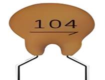
This code means:
- First two digits → base value
- Third digit → multiplier
Therefore:
104 = 10 × 10⁴ pF = 100000 pF = 100 nF.
Understanding these markings helps engineers choose correct components during PCB design and maintenance.
What Does 473 Mean on a Capacitor?
The code 473 is a common capacitor marking used on ceramic capacitors. The coding system follows a three-digit format.
- First two digits → base number
- Third digit → number of zeros added
Calculation example:
473 = 47 × 10³ pF = 47,000 pF.
Converted units:
- 47,000 pF
- 47 nF
- 0.047 μF
This capacitor value often appears in signal filtering and timing circuits.
Small surface-mount capacitors frequently use this numeric system due to limited space for labeling.
How Do I Know Which Capacitor Is the Start and Which Is the Run?
Motor circuits often use two capacitors: start capacitors and run capacitors. Each type performs a different role. Start capacitors provide extra torque during motor startup, run capacitors maintain stable motor operation.
Key differences appear in capacitance value and duty cycle.
| Feature | Start Capacitor | Run Capacitor |
| Capacitance | High | Lower |
| Duty cycle | Short-term | Continuous |
| Application | Motor starting | Motor running |
| Construction | Electrolytic | Film capacitor |
Start capacitors usually operate for a short period during motor startup, run capacitors remain active throughout motor operation.
Is the Black Side of a Capacitor Positive or Negative?
In many electrolytic capacitors, the black stripe marks the negative terminal. This stripe runs along the body of the capacitor. It typically includes minus symbols. However, engineers should confirm polarity using multiple indicators.
Reliable identification methods include:
- Polarity stripe on the capacitor body
- PCB “+” symbol marking
- Lead length differences
- Manufacturer datasheet
Assuming polarity based on color alone can lead to mistakes. Therefore, visual verification combined with documentation remains the safest approach.
In professional electronics manufacturing, polarity verification is part of the quality control process. Experienced PCB and PCBA providers ensure correct capacitor placement through inspection and automated testing.
Best Technology supports engineers with reliable PCB fabrication and PCBA assembly services. The company integrates design review, component sourcing, and assembly verification to ensure stable electronic products.
For PCB or PCBA inquiries, please contact: sales@bestpcb.vn