 language
Fakra Connector PCB Manufacturer | Fast Turnkey PCBA Support
Fakra Connector PCB refers to a printed circuit board designed to integrate FAKRA RF connectors for stable signal transmission in automotive communication systems such as antennas, GPS modules, telematics units, cameras, and ADAS platforms. This article explains the key design principles of Fakra Connector PCB, including VSWR control, frequency capability, connector selection, Mini-FAKRA differences, and how to successfully manufacture RF antenna PCBs with fast turnkey PCBA support.
Best Technology is a reliable manufacturing partner for Fakra Connector PCB projects, providing both technical expertise and fast turnkey PCBA support for RF and automotive electronics applications. Our engineering team understands the critical requirements of RF connector integration, including controlled impedance routing, connector footprint accuracy, grounding structures, and stable solder attachment for FAKRA and Miniature FAKRA connectors.
With extensive experience in PCB fabrication, component sourcing, and RF connector assembly, we help customers develop high-frequency PCB solutions used in antenna modules, telematics systems, vehicle cameras, and ADAS platforms. By combining engineering review, manufacturing precision, and flexible prototype-to-production services, Best Technology ensures every Fakra Connector PCB project moves smoothly from design to delivery. If you are developing an RF antenna or automotive communication system, pls feel free to contact our team anytime at sales@bestpcb.vn to discuss your Fakra Connector PCB project.
Common Pain Points in Fakra Connector PCB Projects
What problems do engineers frequently encounter when designing Fakra Connector PCB for RF antenna systems?
- Connector footprint mismatch leads to assembly problems.
- Poor PCB launch design causes high VSWR and signal reflection.
- Standard FAKRA connectors are too large for compact modules.
- Incorrect PCB material reduces RF signal stability.
- PCB suppliers lack RF connector assembly experience.
Practical Solutions from a Professional PCB Manufacturer
A professional Fakra Connector PCB manufacturer can address these issues through engineering-driven design and manufacturing support.
- Verify connector footprints and mechanical drawings before production.
- Optimize RF launch geometry and impedance transitions.
- Provide Miniature Fakra Connectors PCB options for compact layouts.
- Recommend PCB materials suitable for RF antenna frequencies.
- Offer turnkey PCB fabrication and PCBA assembly services.
Best Technology is a professional PCB and PCBA manufacturer supporting RF antenna systems, automotive communication electronics, and high-frequency circuit boards. Our team provides engineering review, PCB manufacturing, component sourcing, and turnkey PCBA services for Fakra Connector PCB projects. For inquiries, contact sales@bestpcb.vn.
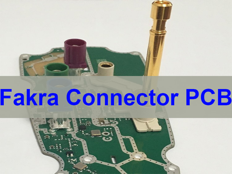
What Is Fakra Connector PCB?
A Fakra Connector PCB is a printed circuit board that integrates FAKRA RF connectors to transmit high-frequency signals between antennas, RF modules, and communication systems.
FAKRA connectors are widely used in automotive RF systems because they provide reliable mechanical locking, standardized impedance, and strong electromagnetic shielding. When mounted on a PCB, the connector becomes part of the RF transmission path, meaning the PCB design directly affects signal performance.
Key characteristics of Fakra Connector PCB
- Controlled impedance routing
Most RF antenna systems require a 50 Ω transmission path from the connector into the PCB trace. - Reliable mechanical connection
Many FAKRA connectors use through-hole solder attachment for stronger mechanical stability. - Shielded RF signal transmission
The connector design provides protection against EMI interference. - Automotive-grade reliability
Fakra connectors are widely used in vehicle electronics such as GPS, telematics, cameras, and infotainment systems. - Integration with RF antenna modules
Fakra Connector PCB is commonly used in antenna amplifiers, radar modules, and wireless communication devices.
In short, the Fakra PCB connector acts as the bridge between the antenna system and the internal RF circuitry.
How Does FAKRA Connector PCB Design Affect VSWR in RF Systems?
VSWR (Voltage Standing Wave Ratio) is a critical indicator of RF signal matching quality. In a Fakra Connector PCB, poor connector launch design or impedance mismatch can cause signal reflection, which increases VSWR and reduces transmission efficiency.
Factors that influence VSWR in Fakra Connector PCB design
- Connector launch transition
The transition between the connector pin and the PCB trace must maintain consistent impedance. - Ground reference design
Ground vias around the connector improve return current flow and reduce RF discontinuities. - PCB trace structure
Microstrip or coplanar waveguide traces are commonly used for RF routing. - Solder joint consistency
Uneven solder joints can slightly disturb the RF electromagnetic field. - PCB material stability
Dielectric constant stability affects impedance consistency and signal integrity.
Simplified VSWR relationship
Where Γ represents the reflection coefficient.
A well-designed Fakra Connector PCB keeps VSWR low, allowing RF antenna systems to operate efficiently across the target frequency band.
What Frequency Range Do FAKRA Connector PCBs Support?
The frequency capability of a Fakra Connector PCB depends on the connector type, PCB material, RF layout quality, and assembly precision.
Standard automotive FAKRA connectors are commonly used for RF signals up to several gigahertz. Newer Miniature Fakra connectors can support higher frequencies and higher data bandwidth.
Typical frequency capability comparison
| Connector Type | Typical Frequency Capability | Common Applications |
|---|---|---|
| Standard FAKRA | Up to ~6 GHz | GPS, telematics, infotainment |
| Enhanced FAKRA systems | Up to ~12 GHz | advanced RF communication |
| Miniature Fakra Connectors PCB | Up to ~9 GHz or higher | ADAS cameras, compact modules |
PCB factors that influence frequency performance
- PCB dielectric loss
- Copper surface roughness
- RF trace geometry
- Grounding structure
- Connector launch design
Therefore, the phrase fakra connectors pcb frequency should always be evaluated based on the entire RF signal path rather than only the connector specification.
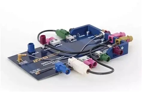
What are The Differences Between Fakra Connectors PCB And Miniature Fakra Connectors PCB?
As automotive electronics become more compact, Miniature Fakra Connectors PCB solutions are becoming increasingly popular.
Mini-FAKRA connectors are smaller and allow higher port density while still maintaining RF signal performance.
Comparison between standard and miniature FAKRA PCB solutions
| Feature | Fakra Connectors PCB | Miniature Fakra Connectors PCB |
|---|---|---|
| Connector size | Larger | Smaller |
| PCB space usage | Moderate | Very compact |
| RF channel density | Limited | Higher |
| Typical automotive use | Traditional telematics systems | Advanced ADAS modules |
| Design complexity | Moderate | Higher precision required |
Miniature Fakra connectors are particularly suitable for radar sensors, camera systems, and compact automotive RF modules.
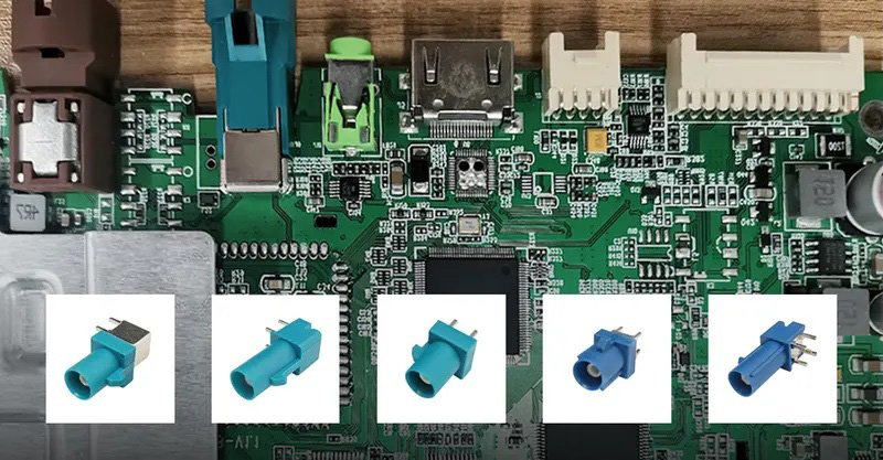
How Should You Choose FAKRA Connectors PCB for an RF Antenna Project?
Choosing the right Fakra Connector PCB for an RF antenna system requires balancing electrical performance, mechanical structure, and manufacturing feasibility.
Key factors when selecting Fakra PCB connector solutions
- Operating frequency band
The antenna frequency determines connector and PCB material requirements. - Mechanical space limitations
Compact modules may require Miniature Fakra Connectors PCB. - Connector mounting type
Through-hole solder attachment provides stronger mechanical support. - PCB impedance control capability
Proper stack-up design ensures signal stability. - Assembly process compatibility
RF connectors require precise soldering and inspection procedures. - Supplier engineering support
A knowledgeable PCB manufacturer can help avoid RF design mistakes.
Selecting the right connector and PCB design early in the project significantly reduces redesign risks.
Why Choose Best Technology for Miniature FAKRA Connector PCB Design and Assembly?
A successful Fakra Connector PCB project requires more than PCB fabrication. It requires coordination between RF design, connector selection, manufacturing, and assembly.
Best Technology supports customers with complete engineering and manufacturing services.
Advantages of working with Best Technology
- RF PCB engineering support
We assist with connector footprint design and RF layout optimization. - Turnkey PCB and PCBA services
PCB fabrication, component sourcing, and assembly are managed together. - Prototype and small batch flexibility
Ideal for RF antenna validation and product development. - Automotive electronics experience
Our processes support automotive communication systems and RF modules. - Fast project coordination
Engineering review and manufacturing preparation are handled efficiently.
For RF antenna developers and automotive electronics manufacturers, this approach reduces supply chain complexity and accelerates product development.
Case About Fakra Connector PCB Fabrication in Best Technology
A customer developing an automotive RF antenna module required a Fakra Connector PCB with compact dimensions and stable RF performance.
Project requirements
- Automotive-grade RF connector integration
- Controlled impedance routing
- Through-hole connector mounting
- Prototype delivery within a short timeline
Engineering approach
- Verified the connector footprint and mechanical drawing.
- Optimized PCB stack-up for RF impedance control.
- Designed ground via structures around the connector launch.
- Selected suitable PCB materials for RF signal transmission.
- Coordinated PCB fabrication and PCBA assembly in one workflow.
Result
The prototype was delivered quickly with stable RF performance and reliable connector soldering, allowing the customer to proceed with antenna validation testing.
PCB Specifications
- PCB Type: RF Fakra Connector PCB
- Layer Count: 2L
- PCB Thickness: 0.8 mm
- Copper Weight: 1/2 oz
- Material: Rogers 4003C High-Frequency Laminate
- Surface Finish: Soft Gold (Au)
- Impedance Control: 50 Ω RF Transmission Line
- Connector Type: FAKRA RF Connector (Through-Hole Mount)
- Application: Automotive RF Antenna Module
In a nutshell, Fakra Connector PCB plays a crucial role in RF antenna systems by enabling reliable signal transmission between antennas and communication modules. This article explained how Fakra Connector PCB design affects VSWR, frequency capability, connector selection, and RF antenna performance.
Best Technology provides professional Fakra Connector PCB manufacturing, engineering support, and turnkey PCBA services for RF communication projects and automotive electronics systems.
If you are developing an RF antenna system or automotive communication module, contact our engineering team at sales@bestpcb.vn for professional Fakra Connector PCB manufacturing support.
FAQs About Fakra Connector PCB
What is a Fakra PCB connector used for?
A Fakra PCB connector is commonly used in automotive RF communication systems such as GPS antennas, telematics modules, and vehicle cameras.
What is the difference between Fakra connectors PCB and Miniature Fakra connectors PCB?
Miniature Fakra connectors are smaller and support higher connector density, making them suitable for compact automotive electronics.
Can a Fakra plug connector solder attachment thru hole pcb design improve reliability?
Yes. Through-hole connectors typically provide stronger mechanical retention compared with surface-mounted RF connectors.
What affects the frequency performance of Fakra connectors PCB?
Frequency performance depends on connector design, PCB material, impedance routing, grounding structure, and assembly precision.