 language
What Is Open CCT? Open Circuit Diagram, Voltage & Current
Open CCT is a commonly used abbreviation for open circuit in electronics and electrical engineering discussions. An open circuit describes a condition where the electrical path is interrupted, preventing current from flowing through the circuit. This situation can occur intentionally, such as when a switch is turned off, or unintentionally due to a broken trace, damaged component, or poor solder connection.
In modern electronics manufacturing, especially in PCB assembly, identifying and preventing open circuit failures is a critical quality requirement. A single open connection can stop an entire device from functioning. For this reason, engineers rely on multiple inspection methods such as AOI, X-ray inspection, and electrical testing to ensure circuit continuity. In this article, we will explore the meaning of open CCT, how open circuits occur, how to test them, and how PCB manufacturers prevent them during production.
What Does Open CCT Mean in Electronics?
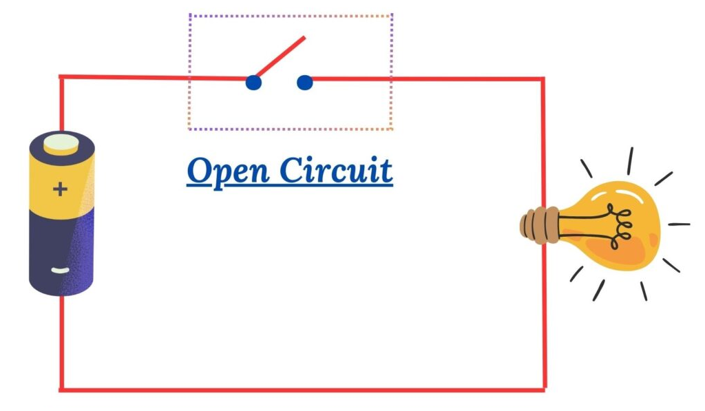
Open CCT simply means open circuit. It refers to a circuit where the electrical path is incomplete, preventing current from flowing between the power source and the load. When a circuit is open, electrons cannot move through the conductive path, so the device connected to the circuit will not operate.
In electronics diagrams and technical discussions, engineers may shorten the term open circuit to “open cct” for convenience. The concept itself is fundamental in circuit analysis. A circuit must form a closed loop for current to flow. If any part of that loop breaks, the circuit becomes open.
A practical example is a light switch. When the switch is turned off, the circuit is open. Electricity cannot reach the light bulb, so the bulb remains off. When the switch is turned on, the circuit becomes closed and current flows normally.
What Is an Open Circuit and How Does It Work?
An open circuit occurs when there is a discontinuity in the electrical path. This interruption stops current from flowing through the system. Even if voltage is present, the circuit cannot deliver electrical energy to the load.
In electrical theory, current requires a complete conductive path. The circuit typically includes a power source, conductive wiring, and a load such as a resistor, motor, or electronic component. If any connection breaks, the circuit becomes open and current drops to zero.
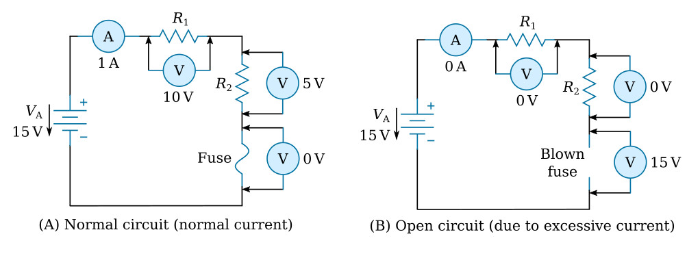
The resistance of an open circuit is considered extremely high, often described as infinite resistance. Because of this high resistance, no meaningful current flows through the system.
In PCB assemblies, open circuits often occur due to damaged copper traces, defective vias, missing components, or poor solder joints. These failures can interrupt signal transmission or power distribution across the board.
What Happens When a Circuit Becomes Open?
When a circuit becomes open, the electrical current stops flowing immediately. The connected device loses power and stops operating. Although voltage may still be present at certain points, the lack of a complete path prevents energy transfer.
For example, if a power supply provides 12 volts to a circuit but a wire breaks between the supply and the load, the voltage may still exist at the source side. However, the load receives no current, so it remains inactive.
In electronic products, open circuits can lead to several noticeable symptoms. The device may fail to power on, sensors may stop responding, or signal communication between components may be interrupted. In complex systems, these failures may appear as intermittent malfunctions.
What Are Common Examples of Open Circuit in Electronics?
Open circuits can appear in many different electronic systems. They occur whenever the conductive path between components is interrupted.
Common examples include:
- A broken wire in a cable harness
- A disconnected battery terminal
- A damaged PCB copper trace
- A cracked solder joint
- A defective switch left in the open position
- A blown fuse interrupting current flow
In PCB manufacturing, open circuit failures frequently occur in fine traces or microvias. Mechanical stress, thermal expansion, or manufacturing defects can cause these conductive paths to break.
What Causes an Open Circuit in Electronic Devices?
Open circuits can result from multiple mechanical, electrical, or manufacturing issues. Identifying the root cause is essential for reliable troubleshooting.
The most common causes include:
- Broken wires or damaged connectors
- Poor solder joints or cold solder connections
- Cracked PCB traces
- Defective components with internal discontinuities
- Thermal stress causing solder fatigue
- Corrosion or oxidation of conductive surfaces
In high-density PCB assemblies, very small copper traces can be vulnerable to mechanical damage. During manufacturing or handling, bending or excessive force may break these traces and create an open circuit.
Another frequent cause is insufficient solder during SMT assembly. If the solder joint fails to properly connect a component lead to the pad, the electrical path becomes open.
How Do Engineers Test an Open Circuit?
Engineers use several methods to detect open circuits during design validation, troubleshooting, and manufacturing quality control.
The most widely used testing methods include:
- Continuity testing using a multimeter
- Automated Optical Inspection (AOI)
- X-ray inspection for hidden solder joints
- In-circuit testing (ICT)
- Flying probe electrical testing
- Functional system testing
Each method focuses on different aspects of the circuit. For example, AOI detects missing components or solder defects, while ICT verifies electrical connectivity across the board.
Flying probe testers are particularly useful for prototype or low-volume PCB production because they can test connectivity without requiring a dedicated fixture.
How to Check Open Circuit Using a Multimeter?
A multimeter is one of the simplest tools used to detect open circuits. Engineers typically use the continuity test function or resistance measurement mode.
The basic testing process includes the following steps:
1. Turn off the power supply to the circuit.
2. Set the multimeter to continuity mode.
3. Place the test probes on two points of the circuit path.
4. If the circuit is continuous, the multimeter will produce a beep sound.
5. If the circuit is open, the meter will show infinite resistance or no signal.
This method is widely used in field repairs, prototype debugging, and laboratory testing. However, it requires physical access to the circuit nodes being tested.
What Is Open Circuit Voltage and Why Is It Important?
Open circuit voltage, often abbreviated as OCV, refers to the voltage measured across the terminals of a device when no load is connected. In other words, it is the voltage present when the circuit is open and no current flows.
This measurement is important in many electrical systems, especially batteries and solar panels. The open circuit voltage indicates the potential electrical energy available from the source.
For example, when testing a battery, measuring the open circuit voltage can provide a quick indication of its charge level and health. Engineers often compare OCV values with nominal voltage specifications to evaluate performance.
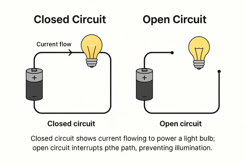
Open Circuit vs Closed Circuit: What Is the Difference?
Understanding the difference between open and closed circuits is essential for electrical troubleshooting and system design.
| Type of Circuit | Current Flow | Resistance | Typical Example |
|---|---|---|---|
| Open Circuit | No current flows | Extremely high resistance | Broken wire or disconnected switch |
| Closed Circuit | Current flows normally | Normal resistance | Operating electrical device |
In a closed circuit, electricity flows from the power source through the load and returns to the source. In an open circuit, this loop is interrupted.
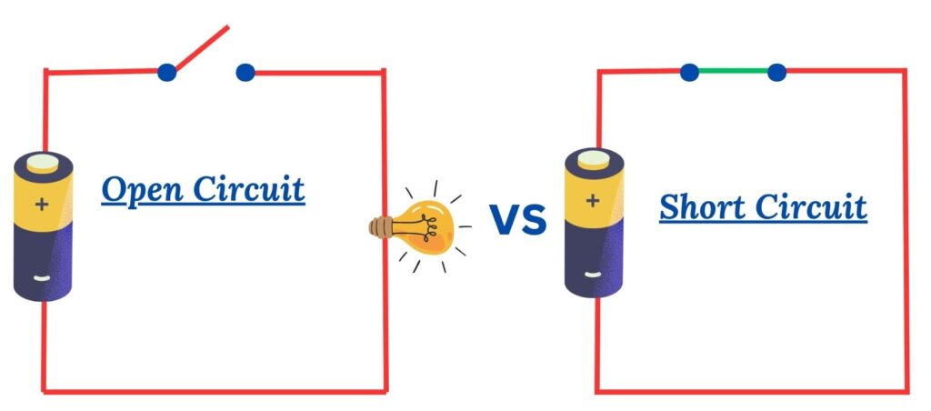
Short Circuit vs Open Circuit: Key Differences
Open circuits and short circuits are two common electrical faults, but they behave very differently.
| Condition | Current Behavior | Resistance Level | Typical Result |
|---|---|---|---|
| Open Circuit | No current flow | Very high resistance | Device stops operating |
| Short Circuit | Excessive current flow | Very low resistance | Possible overheating or damage |
An open circuit interrupts the current path, while a short circuit creates an unintended low-resistance path that allows excessive current to flow. Both conditions can affect electronic systems, but their causes and troubleshooting methods are different.
How Do PCB Manufacturers Prevent Open Circuits?
Preventing open circuits is a major focus in PCB manufacturing and assembly processes. Manufacturers implement strict inspection and testing procedures to ensure reliable electrical connectivity.
Typical prevention strategies include:
- Design for Manufacturability (DFM) analysis before production
- Automated Optical Inspection after soldering
- X-ray inspection for hidden BGA solder joints
- Flying probe testing for continuity verification
- In-circuit testing for electrical validation
- Functional testing for final product performance
Professional PCB assembly providers integrate these inspection stages into the manufacturing workflow to ensure that every connection on the board meets reliability standards.
At Best Technology, engineers combine PCB fabrication, component sourcing, SMT assembly, and system testing into one integrated manufacturing process. This structured workflow allows early detection of potential open circuit risks while improving product reliability and production efficiency.
FAQs About Open CCT and Open Circuits
What is open circuit voltage?
Open circuit voltage is the voltage measured across a device when no load is connected and no current flows through the circuit.
How do you detect an open circuit?
An open circuit can be detected using a multimeter continuity test, electrical testing equipment, or PCB inspection tools such as flying probe testers.
What causes open circuits in PCB assemblies?
Common causes include broken traces, cold solder joints, defective components, damaged vias, and manufacturing defects.
Is an open circuit dangerous?
In most cases, an open circuit simply stops current flow and disables the device. However, it can lead to system failure in critical equipment.
What tool is used to test open circuits?
Multimeters, continuity testers, flying probe systems, and in-circuit testers are commonly used to detect open circuits.
Can an open circuit damage electronic devices?
An open circuit usually prevents operation rather than causing damage, but in some systems it may disrupt control signals or safety functions.
Conclusion
Open CCT, or open circuit, is one of the most fundamental concepts in electronics. It describes a situation where the electrical path is interrupted and current cannot flow. Understanding how open circuits occur, how they affect electronic systems, and how they can be detected is essential for engineers, technicians, and PCB manufacturers.
Through proper circuit design, thorough testing procedures, and reliable manufacturing processes, open circuit failures can be minimized. Modern PCB assembly facilities use advanced inspection technologies to ensure that every connection meets strict reliability standards.
If you are developing electronic products and need reliable PCB fabrication or PCBA assembly services, working with an experienced manufacturing partner can significantly improve product stability and reduce troubleshooting time.
For professional PCB and PCBA support, feel free to contact our engineering team at: sales@bestpcb.vn